Quantcast
Channel: temperature | Battery Guide
Viewing all 365 articles
Browse latest View live

Basic Temperature Control for Refrigerators

$
0
0

This design is a basic temperature control for refrigerators that has an electromechanical circuit. It specifically uses MC9RS08KA4CWJR microcontroller which has an 8-bit RS08 central processing unit, 254 bytes RAM, 8Kbytes flash, two 8-bit modulo timers, 2-channel 16-bit Timer/PWM, inter-integrated circuit BUS module, keyboard interrupt, and analog comparator. This project effectively controls temperature of any device using resistors and capacitors.

Basic Temperature Control for Refrigerators

The refrigerator temperature control is a basic RC network connected to an I/O pin. A variable resistor (potentiometer) is used to modify the time the capacitor takes to reach VIH and adjusting its resistance varies that time. A basic voltage divider with one resistor and one thermistor is used to implement the temperature sensor. The thermistor resistance depends on the temperature. For each temperature, we have a different voltage in the divider. This value is effectively measured with the Analog-to-Digital Converter (ADC) implemented by software that uses one resistor, one capacitor, and the analog comparator. In addition, VDD and VSS are the primary power supply pins for the MCU. This voltage source supplies power to all I/O buffer circuitry and to an internal voltage regulator. The internal voltage regulator provides a regulated lower-voltage source to the CPU and other MCU internal circuitry.


For more detail: Basic Temperature Control for Refrigerators

The post Basic Temperature Control for Refrigerators appeared first on PIC Microcontroller.


Voltage, Temperature & Frequency Meter With PIC Micro controller

$
0
0

Features…

  • Voltage, Temperature and Frequency can switching to each others using push buttons.
  • Voltage Meter can measure DC voltage between 0v to 50v.
  • Frequency Meter can measure frequency up to 65KHz.
  • Temperature Meter can use between 00C to 1500C.
  • Every functions can paused using push button.

Voltage, Temperature & Frequency Meter With PIC Micro controller

Instructions…

Voltage meter – 

Volt meter can measure dc voltages up to 50v. 5V is the maximum voltage can handle PIC microcontroller, as it is voltage divider (10K,1.1K) use for convert 50V to 5V . 5v zener diode use for safety of PIC microcontroller analog input pin.

Temperature meter – 

Temperature meter can use between 00C to 1500C. But LM35 sensor can use between -550C to 1500C. Sensor’s resistant is changing opposite to temperature, as it is maximum temperature gives maximum voltage output(5v)  and minimum temperature gives minimum voltage output(0v).  

Frequency meter – 

Theoretically, frequency meter can use up to 65KHz, that is because this circuit made by using Timer 1(16bit) of PIC microcontroller.

Voltage, Temperature & Frequency Meter With PIC Micro controller schematicTimer 0 can only measure up to 256Hz, that is because timer 0 is 8 bit timer. Transistor part is use for safety of microcontroller from amplitude of wave signal. This circuit can apply 12v amplitude or more changing transistor base resistor value(4.7K). I tested it, using 12v amplitude square wave signal

Troubleshooting…

If you have problem about accuracy of voltmeter, temperature meter and frequency meter, you can change values (*1,*2,*3)


For more detail: Voltage, Temperature & Frequency Meter With PIC Micro controller

Current Project / Post can also be found using:

  • temperature measurement project

The post Voltage, Temperature & Frequency Meter With PIC Micro controller appeared first on PIC Microcontroller.

Interfacing LM35 Temperature Sensor with PIC Microcontroller.

$
0
0

The are many cool sensors available now a days, ranging from IR distance sensor modules, accelerometers, humidity sensors, temperature sensors and many many more(gas sensors, alcohol sensor, motion sensors, touch screens). Many of these are analog in nature. That means they give a voltage output that varies directly (and linearly) with the sensed quantity. For example in LM35 temperature sensor, the output voltage is 10mV per degree centigrade. That means if output is 300mV then the temperature is 30 degrees. In this tutorial we will learn how to interface LM35 temperature sensor with PIC18F4520 microcontroller and display its output on the LCD module.

Interfacing LM35 Temperature Sensor with PIC MicrocontrollerFirst I recommend you to go and read the following tutorial as they are the base of this small project.

After reading the ADC tutorial given above you will note the the PIC MCU’s ADC gives us the value between 0-1023 for input voltage of 0 to 5v provided it is configured exactly as in the above tutorial. So if the reading is 0 then input is 0v, if reading is 1023 then input is 5v. So in general form if the adc read out is val then voltage is.

unsigned int val;
val=ADCRead(0); //Read Channel 0
voltage= ((val)/1023.0)*5;

The above formula give voltage in Volts, to get Voltage in mili Volts (mV) we must multiply it with 1000, so

voltage=((val)/1023.0)*5*1000); //Voltage is in mV

since 10mV = 1 degree, to get temperature we must divide it by 10, so

t=((val)/1023.0)*5*100); //t is in degree centigrade

simplifying further we get

t=((val/1023.0)*500);
t=(val*0.48876);

we round off this value, so

t=round(val*0.48876);

remember round() is a standard c library function

Interfacing LM35 Temperature Sensor with PIC Microcontroller schematicHardware for LM35 based thermometer.

You will need a PIC18F4520 chip running at 20MHz attached with a standard 16×2 LCD Module and LM35 on AN0 pin. LM35 is a 3 pin device as show below.

connect the +Vs Pin to 5v and GND to GND. The output must be connected to the analog input pin 0 of the PIC18F4520 MCU. It is labeled AN0 in the datasheet. It is pin number 2 on the 40 pin package. It is also called RA0 because it is shared with PORTA0.

We will use our 40 PIN PIC Development board to realize the project. The base board has all the basic circuit to run the PIC. The extra part required for this project like LCD and the LM35 temperature sensor are installed in the expansion board.


For more detail: Interfacing LM35 Temperature Sensor with PIC Microcontroller.

Current Project / Post can also be found using:

  • Circuit for fire fighting robot using pic mcro 16f887a

The post Interfacing LM35 Temperature Sensor with PIC Microcontroller. appeared first on PIC Microcontroller.

Temperature Indicator using PIC microcontroller

$
0
0

Hi friends, today we will see how to make temperature indicator using PIC microcontroller. The basic aim of this project is make you familiar with PIC microcontroller. It also explains how LM35 and 7 segment displays can be interfaced with PIC microcontroller.

Components required:

Following is a list of components required for temperature indicator using PIC microcontroller – mini project:
Temperature Indicator using PIC microcontroller

  • PIC microcontroller (PIC16F676)
  • 4 digit (or 3digit) seven segment display (Common cathode)
  • Temperature sensor (LM35) IC
  • 5V DC power supply

Circuit diagram:

Following figure shows circuit diagram of temperature indicator using PIC microcontroller.

Theory:

In this mini project we have used PIC microcontroller and a four digit seven segment display is interfaced with it. For sensing the surrounding temperature we have used a temperature sensing IC i.e. LM35. You can use a voltmeter to crosscheck whether the indictor giving correct output or not. The output of the temperature in terms of volts will be in the range of mV.

Temperature Indicator using PIC microcontroller SchematicWorking of LM35:

LM35 is an integrated temperature sensor. It produces output voltage proportional to the temperature. The advantage of using LM35 is that it does not require any external calibration technique and it has accuracy of ±0.4 degree Celsius at room temperature. It draws only 60µA from supply and possesses low self heating. Thus the chances of error get minimized.


For more detail: Temperature Indicator using PIC microcontroller

The post Temperature Indicator using PIC microcontroller appeared first on PIC Microcontroller.

Search Results for: Temperature Controlled Fan using 8051 Microcontroller …

$
0
0

Temperature Controlled Fan Report – SlideShare – Temperature controlled fan regulator – electronic circuits, 33 thoughts on “ temperature controlled fan regulator ” siddhu march 12, 2015 at 7:00 am. i didn’t find 100k ptc,5k ptc where are they available and does the. Android controlled robot 8051 microcontroller, Android controlled robot using 8051 and bluetoothour robot expert gaurav khadasane has come up with another innovative way to control a robot. he is controlling his. 8051 microcontroller projects electronics engineering, Edgefx is a top 8051 projects online seller in india. we provide a huge list of microcontroller based projects on 8051 microcontroller with free abstracts..

Search Results for Temperature Controlled Fan using 8051 Microcontroller ... Temperature controlled fan speed – projects 8051, Description: temperature controller can be done by using electronic circuit, microprocessor or microcontroller. now microcontroller is advanced among all above.Temperature based speed control fan microcontroller, Design an automatic temperature control system for smart electric fan using pic.Temperature controlled dc fan – electronic circuits , Description. here is a simple circuit based on two transistors that can be used to control the speed of a 12 v dc fan depending on the temperature.a thermistor (r1.Temperature controlled fan report – slideshare, “temperature controlled fan” a project report submitted by peeyush pashine.

Temperature control system lm35 precision – youtube, One of my 3rd year microcontroller lab projects was to realize a temperature control system using an 8 bit, 80c51 family chip. the schematic contains the.Temperature controlled fan regulator – electronic circuits, 33 thoughts on “ temperature controlled fan regulator ” siddhu march 12, 2015 at 7:00 am. i didn’t find 100k ptc,5k ptc where are they available and does the.
Search Results for Temperature Controlled Fan using 8051 Microcontroller ... Schematic8051 microcontroller projects electronics engineering, Edgefx is a top 8051 projects online seller in india. we provide a huge list of microcontroller based projects on 8051 microcontroller with free abstracts..

For more detail: Search Results for: Temperature Controlled Fan using 8051 Microcontroller …

Current Project / Post can also be found using:

  • how to make temperature measuring project
  • measurement projects with microcontroller
  • measurment projects by microcontroller
  • pic16f887 based measurement project

The post Search Results for: Temperature Controlled Fan using 8051 Microcontroller … appeared first on PIC Microcontroller.

Interfacing Temperature Sensor with Microchip PIC16F876A

$
0
0

The tutorial aims at providing the necessary information for interfacing an analog type temperature sensor with a Microchip PIC Microcontroller. PIC (Peripheral Interface Controllers) was introduced in 1985. The PIC16F876A has 8K of Flash Program Memory, 368 bytes of Data Memory (RAM) and many other attractive features. Some features are ADC, USART, and 14 Interrupts all in 28 PDIP Package.

mperature Sensor with Microchip PIC16F876AThe Analog temperature sensor used is LM35. It has a transfer function of 10mv/’c. The output of LM35 is analog voltage which varies with changes in temperature. This analog voltage is digitized using the On-Chip 10bit A/D Converter and the value is displayed on a 2×16 LCD.

It is possible to switch On/Off an external application based on temperature value.

The LCD is based on HD44780 controller. The programming has been done using the MikroC compiler from Mikroelektronika (www.mikroe.com). The demo version has a 2KB Hex Output limit, fortunately it is more than enough for our requirement.

Program

int t1,temp;

char *text[6];

void main()

{adcon1=14;

lcd_init(&portb);

lcd_out(1,1,”Temperature”);

lcd_out(2,8,”‘C”);

while(1)

{t1=adc_read(0);

//temp=0.245*t1;          // For TMP37 Sensor 20mv/’c

temp=0.245*t1*2;        // For Lm35 Sensor 10mv/’c

inttostr(temp,text);

lcd_cmd(lcd_cursor_off);

lcd_out(2,1,text);

delay_ms(100);}}

Interfacing Temperature Sensor with Microchip PIC16F876A SchematicThe program is self explanatory, however let me explain you the calculation done. In a while loop. The Input channel 0 is read and the digitized value is obtained. Now the smallest digitized value is equal to Vref/((2^10)-1). Internal Vref is 4096mV but we will consider 5000mV for the ease of calculation. Multiplying the value obtained above with the digitized value will give us the analog voltage. Since the transfer function of Lm35 is 10mV/’c, we can obtain the temperature.


For more detail: Interfacing Temperature Sensor with Microchip PIC16F876A

The post Interfacing Temperature Sensor with Microchip PIC16F876A appeared first on PIC Microcontroller.

Maxim adds mosfets to ‘smallest’ DC-DC converter

$
0
0

Description

Create a design and simulate using EE-Sim: [MAX15058]

The MAX15058 high-efficiency, current-mode, synchronous step-down switching regulator with integrated power switches delivers up to 3A of output current. The device operates from 2.7V to 5.5V and provides an output voltage from 0.6V up to 94% of the input voltage, making the device ideal for distributed power systems, portable devices, and preregulation applications.

The MAX15058 utilizes a current-mode control architecture with a high-gain transconductance error amplifier. The current-mode control architecture facilitates easy compensation design and ensures cycle-by-cycle current limit with fast response to line and load transients.

The MAX15058 offers selectable skip-mode functionality to reduce current consumption and achieve a higher efficiency at light output load. The low RDS(ON) integrated switches ensure high efficiency at heavy loads while minimizing critical inductances, making the layout design a much simpler task with respect to discrete solutions. Utilizing a simple layout and footprint assures first-pass success in new designs.

The MAX15058 features a 1MHz, factory-trimmed, fixed-frequency PWM mode operation. The high switching frequency, along with the PWM current-mode architecture, allows for a compact, all-ceramic capacitor design.

Maxim adds mosfets to ‘smallest’ DC-DC converter

Key Features

  • Internal 30mΩ (typ) RDS(ON) High-Side and 18mΩ (typ) Low-Side MOSFETs at 5V
  • Continuous 3A Output Current Over Temperature
  • 95% Efficiency with 3.3V Output at 3A
  • 1% Output Voltage Accuracy Over Load, Line, and Temperature
  • Operates from 2.7V to 5.5V Supply
  • Cycle-by-Cycle Overcurrent Protection
  • Adjustable Output from 0.6V to Up to 0.94 x VIN
  • Programmable Soft-Start
  • Factory-Trimmed, 1MHz Switching Frequency
  • Stable with Low-ESR Ceramic Output Capacitors
  • Safe-Startup Into Prebiased Output
  • External Reference Input
  • Skip-Mode Functionality
  • Enable Input/Power-Good Output
  • Fully Protected Against Overcurrent and Overtemperature
  • Input Undervoltage Lockout

Maxim claims to have designed the smallest current-mode, synchronous DC-DC converter capable of delivering up to 18A of output current.

The DC-DC regulator integrates the mosfets in a wafer-level package measuring just 2mm x 3.5mm.

The converter can operate in fixed pulse-width modulation (PWM) mode or configured for pulse-skip mode, which means it can cut power during light load conditions.

There are four converters in the range – MAX15058/MAX15108/MAX15112/MAX15118 operate from a 2.7V to 5.5V input voltage with output current of 3, 8, 12, and 18A, respectively. They are designed to provide ±1% output-voltage accuracy over load, line, and temperature.


For more read: Maxim adds mosfets to ‘smallest’ DC-DC converter

The post Maxim adds mosfets to ‘smallest’ DC-DC converter appeared first on PIC Microcontroller.

Digital Temperature Sensor Circuit

$
0
0
Temperature sensors are widely used in electronic equipments to display the temperature. You can see the digital clock displaying the room temperature value. It is due to the temperature sensor embedded in it. Generally, temperature value is analog. It is converted to digital value and then it is displayed. This article describes the same converting analog value to a digital value.Digital Temperature Sensor Circuit

Digital Temperature Sensor Circuit Principle:

The main principle of this circuit is to display the digital temperature value. Here, ATmega8 microcontroller is used. The ATmega8 has inbuilt analog to digital converter with six multiplexed channels. This reduces interfacing of external analog to digital converter IC. The analog temperature value is directly applied to input ADC channels of microcontroller. Successive approximation method is used for Analog to digital conversion internally.

Digital Temperature Sensor Circuit Diagram:

Circuit Components:
  • Resistors – R1 to R7 having the value of 330 Ohms each.
  • LM35 Temperature sensor
  • ATmega8 Microcontroller
  • 7 Segment Display

Digital Temperature Sensor Circuit Design:

The digital temperature circuit consists of ATmega8 microcontroller, LM35 temperature sensor, 7 segment display. The temperature sensor Lm35 is connected to one of the ADC channels of microcontroller.Digital Temperature Sensor Circuit schematic
ATmega8 has six ADC channels at Port C. PC0-PC5 pins of Atmega8 act as ADC channels. This shows that one can interface six analog values. But only one conversion is done at a time depending on the priority of the input channels. The resolution of ADC is 10 bit. Remember that for conversion Vref and Avcc are externally connected as shown in circuit.
Generally, all the port pins of ATmega8 microcontroller act as normal input /output pins until their special functions are declared. ADC registers inside the controller have to be declared in order make Port C to act as ADC channel.
Lm35 temperature sensor has three terminals. Placing the flat surface towards you first pin is Vcc, Second pin is Output and the third pin is Ground. Output pin of temperature sensor is connected to the first ADC channel i.e. PC0 pin of microcontroller.
Seven segment display has eight pins and one common pin. Leaving Dp, connect all the seven pins to port B. Connect A to PB0, B to PB1,_____, G to PB6. Seven segment display used here is common cathode display. Current limiting resistors were used between controller and the display.


For more detail: Digital Temperature Sensor Circuit

Current Project / Post can also be found using:

  • picd “leds
  • leds and sound on pic 16f84a
  • micrcntroller pic led project list of pdf com
  • pic microcontroller projecgs for 8 to 8 led metric

The post Digital Temperature Sensor Circuit appeared first on PIC Microcontroller.


chipKIT Project 2: Temperature and relative humidity logger

$
0
0

This project is about building a PC-based temperature and relative humidity logger using the chipKIT Uno32 board and the DHT11 sensor. The project setup requires no additional wires (other than the USB cable) and components; the DHT11 sensor is directly plugged into four I/O pins of the Uno32 board and the project is ready to go. This could be a handy and an easiest way to setup an ambient room monitoring system for a server room. The Uno32 reads the temperature and relative humidity from the DHT11 sensor at preset interval and sends the data to PC through the USB-UART interface. A PC application is developed using the open-source Processing programming platform to log data onto an ASCII file. The PC application also displays the real-time temperature and relative humidity on computer screen.

PC-based logger for temperature and relative humidity

PC-based logger for temperature and relative humidity

Theory

Measurement of temperature and relative humidity using DHT11 sensor and PIC microcontroller for more details on the DHT11 communication protocol. The following picture describes the four pins of the DHT11 sensor.In this project, four pins of the DHT11 sensor is directly inserted into four I/O pins (7, 6, 5, and 4) of the Uno32 board. The power supply (1), data (2), and ground (4) pins of DHT11 go to I/O pins 7, 6, and 5 of the Uno32, respectively. The Uno32 pins 7 and 4 are configured as output pins and are set to High (3.3V) and Low (Gnd), respectively, through software to power the DHT11 sensor.

DHT11 pins

DHT11 pins


Inserting DHT11 on to I O pins 7-4 of Uno32

Inserting DHT11 on to I O pins 7-4 of Uno32


Complete setup of the project

Complete setup of the project

Note that an I/O pin of Uno32 can source up to 18mA current that is sufficient to power the DHT11 sensor, which only requires less than 5mA during data conversion and transfer. Pin 3 of DHT11 is unused. Temperature and humidity bytes are read through I/O pin 6 of the Uno32.

chipKIT sketch

Writing firmware is easier with the use of the DHT11 library available for Arduino or chipKIT platform. The DHT11 library for Arduino was originally written by George Hadjikyriacou and was later modified by other people. Make sure you include the library in your chipKIT sketch. The following sketch is for Uno32 to read the temperature and relative humidity data (two bytes) from the DHT11 and send them over the serial port. The sampling interval is set to 2 seconds.

/*
  Project 2:   PC-based temperature and humidity logger
  Description: The DHT11 sensor is used to measure the ambient
               temperature and relative humidity. The measured
               values are displayed on a PC and logged into a ASCII
               file through an application written using Processing.
  Board: chipKIT UNO32
 */
#include "dht11.h"
 
#define VCCPIN      7
#define DHT11PIN    6
#define GNDPIN      4
dht11 DHT11;
void setup()
{
  Serial.begin(9600);
  pinMode(VCCPIN, OUTPUT);
  pinMode(GNDPIN, OUTPUT);
  digitalWrite(VCCPIN, HIGH);
  digitalWrite(GNDPIN, LOW);
}/*--(end setup )---*/
 
void loop()
{
  int chk = DHT11.read(DHT11PIN);
  Serial.write(DHT11.humidity);
  Serial.write(DHT11.temperature);
  delay(2000);
}

Download the complete chipKIT sketch and library files

On PC’s side, the open source programming language Processing is used to develop an graphical application to display the received temperature and humidity information. Processing is an open-source software development environment designed for simplifying the process of creating digital images, animations and interactive graphical applications. It is free to download and operates on Mac, Windows, and Linux platforms. I have written a simple application here that receives the temperature and humidity bytes sent by the Uno32 board through the serial port, and display those information on a graphical window. The data logging part records the temperature and humidity samples plus date and time stamps on an ASCII file. The date and time are based on the PC’s RTC.

You should import the Processing Serial library first before accessing the serial port. This can be done by,

import processing.serial.*;

Next, you can open a serial port as

Dev_Board = new Serial(this, "COM12", 9600);

In my case the USB-UART module on Uno32 board appears as COM12. You should find the right COM number to make it work for you. In Windows machine, you can find this information from the Device Manager tool.

A clickable Start/Stop button is provided on the display window. The Processing Mouse functions are used to detect a mouse press over the button. When the Start is pressed, data logging begins and the label on the button changes to ‘Stop’. If Stop is pressed, the data logging is paused. The temperature samples are recorded along with the date and time stamp (from PC) into an ASCII file. Every time the Start is pressed, the program creates a new ASCII log file. The name of the file contains the current system date and time so that there won’t be any overwriting of files. However, the data are temporarily stored into the PC’s RAM and are transferred to the ASCII file on the hard drive only after pressing the Stop button.

Download the Processing source and applications

Output on computer screen

Output on computer screen

Here’s a sample of the output ASCII file where the temperature and relative humidity information are logged along with the time stamps.

Output record file

Output record file

The data from the log file can be read and plotted to generate graph using applications like MS Excel, or even the given Processing code can be modified further to plot the temperature and relative humidity vs time.

The post chipKIT Project 2: Temperature and relative humidity logger appeared first on PIC Microcontroller.

Simple and small temperature fan controll

$
0
0

Some notes:

1. The C3 can be omitted, its purpose was to filter noises picked up by connecting cable between board and sensing transistor, but as the transistor is mounted on the board it become unnecessary.

Simple and small temperature fan controll
2. R8 is optional and is for reducing the fan speed. Its value must be calculated according the fan current rating and the shorting track bellow it must be cut with sharp knife.
3. When mounting, make sure the board is not touching the heat sink. There are two mounting holes – the one above the sensing transistor and one in opposite corner. I suggest to use a 4mm nut or other similar spacer between the transistor and the board.
4. If there must be electrical insulation between transistor and heat sink, I suggest using transistor with insulated package like MJE350. If not, then BD140 will do the work.
5. Instead of fan you can connect a 12V relay which can do some other job, for example disconnecting appliance from power or connecting bigger fan(s).
6. Trimmer R2 adjust the temperature at which the board switch on. There is hysteresis of 5-10 degrees between switch on and switch off temperatures.
7. Zener diode D1 can be BZX79C7V5 or BZX55C7V5 or 1N4737.

The post Simple and small temperature fan controll appeared first on PIC Microcontroller.

Temperature and relative humidity display with adaptive brightness control using PIC12F683

$
0
0

The objective of this project is to illustrate a technique of implementing adaptive brightness control to seven segment LED displays. It consists of a closed loop system that continuously assesses ambient light condition using an inexpensive light-dependent resistor (LDR) and uses that information to adjust the brightness of the display. For the proof of concept, the technique is applied to construct a digital temperature and relative humidity meter that adapts the brightness of the seven segment LED displays to the surrounding lighting conditions.

Temperature display

There are 8 seven segment LED displays used in this project and they are all driven by one MAX7219 chip. The ambient temperature and relative humidity are measured using the DHT11 sensor. The microcontroller used in this project is PIC12F683, which is a low-pin-count (8) device from 8-bit PIC microcontroller family. Auto-adjusting the brightness of the seven-segment LED display with surrounding illumination enhances the readability in all ambient lighting conditions.

Theory and circuit setup

Many smartphones, HDTVs, PDAs, tablets, and computer screens now come with an automatic brightness control that aims to conserve power as well as to make the display easier to see in a broad range of illumination conditions. This feature basically dims the display screen in a dark environment and brightens it when the ambient light level is higher. The brighter screen helps to counteract the effects of glare from ambient light and also takes into account for the decreased sensitivity of human eyes to brightness as the ambient light level increases.

An automatic brightness adjustment is basically a closed loop system that has the capability to assess ambient light and adjust the brightness of the display accordingly. In our project, a general purpose LDR and a fixed value resistor (10K) are connected in series between the power supply and ground pins to create a voltage dividing network, as shown in the circuit diagram below. The resistance of a typical LDR is less than 1 KΩ under bright lighting condition. Its resistance could go up to several hundred KΩ under extremely dark condition. Therefore, the voltage across the 10K resistor increases proportionally with the surrounding illumination. For the given setup, the voltage across the 10K resistor can vary from 0.1V (under dark condition) to over 4.0V (under very bright illumination). The PIC12F683 microcontroller reads this analog voltage through its AN3 (GP4) ADC channel and then sends out appropriate signals to the MAX7219 display driver to adjust the brightness of the seven segment LED displays.

The MAX7219 chip provides a serial interface to drive 7-segment LED displays (common-cathode type) up to 8 digits and requires only 3 I/O pins from microcontroller. Included on the chip are a BCD decoder, multiplex scan circuitry, segment and digit drivers, and an 8×8 static RAM to store the digit values. The segment current for all LEDs is set through only one external resistor connected between the ISET pin and power supply. However, the device also provides a digital control of the display brightness (16 steps from minimum to maximum) through an internal pulse-width modulator. To learn more about the MAX7219 device, read my previous article Serial 4-digit seven-segment LED display. In this project, the GP0, GP1, and GP2 I/O pins of PIC12F683 are used to drive LOAD, DIN, and CLK signal lines of the MAX7219.

In order to measure the temperature and relative humidity, the DHT11 sensor is used. It can measure temperature from 0-50 °C with an accuracy of ±2°C and relative humidity ranging from 20-95% with an accuracy of  ±5%. The sensor provides fully calibrated digital outputs for the two measurements. It has got its own proprietary 1-wire protocol, and therefore, the communication between the sensor and a microcontroller is not possible through a direct interface with any of its peripherals. The protocol must be implemented in the firmware of the MCU with precise timing calculations required by the sensor. I have described more about this sensor and its communication protocol in Measurement of temperature and relative humidity using DHT11 sensor and PIC microcontroller. The PIC12F683 uses the GP5 I/O pin to communicate with the DHT11.

To make prototyping easier, I am using my PIC12F Project board and my Serial 8-digit seven segment LED display in this project.


For more detail: Temperature and relative humidity display with adaptive brightness control using PIC12F683

Current Project / Post can also be found using:

  • pic16f 628 temperature monitor with PTC sensor

The post Temperature and relative humidity display with adaptive brightness control using PIC12F683 appeared first on PIC Microcontroller.

Humidity and temperature measurements with Sensirion’s SHT1x/SHT7x sensors (Part 1) using pic microcontoller

$
0
0
Temperature and relative humidity are two very important ambient parameters that are directly related to human comfort. Sometimes, you may be able to bear higher temperatures, if there is a lower relative humidity, such as in hot and dry desert-like environment. However, being in a humid place with not very high temperature may make you feel like melting. This is because if there is high relative humidity, sweat from our body will evaporate less into the air and we feel much hotter than the actual temperature. Humidifiers and dehumidifiers help to keep indoor humidity at a comfortable level. Today we will discuss about Sensirion’s SHT series of digital sensors, more specifically SHT11 and SHT75, which are capable of measuring both temperature and relative humidity and provide fully calibrated digital outputs. We will interface both the sensors to PIC18F2550 microcontroller and compare the two sets of  measurements to see the consistency between the two sensors. This tutorial is divided into two parts. The first part will cover all the details regarding the sensors, including their specification, interface, and communication protocol. The second part will be more focussed on the circuit diagram, implementation of the communication protocol with PICMicro, and the results.
Humidity and temperature measurements with Sensirion’s SHT1x SHT7x sensors (Part 1)Theory

Sensirion offers multiple SHT series of digital sensors for measuring both relative humidity and temperature. The temperature is measured using a band-gap sensor, whereas the humidity sensor is capacitive; which means the presence of moisture in air changes the dielectric constant of the material in between the two plates of a parallel-plate capacitor, and hence varies the capacitance. The required signal conditioning, analog-to-digital conversion, and digital interface circuitries are all integrated onto the sensor chip. The various SHT series sensors have different levels of accuracy for humidity and temperature measurements, as described below.

SHT1x are available in surface mount type whereas SHT7x are supplied with four pins which allows easy connection. The SHT11 and SHT75 sensors both provide fully calibrated digital outputs that can be read through a two-wire (SDA for data and SCK for clock) serial interface which looks like I2C but actually it is not compatible with I2C. An external pull-up resistor is required to pull the signal high on the SDA line. However, the SCK line could be driven without any pull-up resistor. The signaling detail of the serial bus is described in the datasheet, which we will implement for PIC18F2550 microcontroller using mikroC pro for PIC compiler. The operating range of both the sensors is 0 to 100% for relative humidity, and -40.0 to 123.8 °C for temperature. The sensor consumes 3 mW power during measurement, and 5 ?W, while in sleep mode.

The SHT11 module that I have got is from mikroElektronika. The sensor (SMD) is soldered on a tiny proto board with all the four pins accessible through a standard 0.1 inch spacing male header. The board comes with pull-up resistors connected to both SDA and SCK lines. One concern in this type of arrangement is the heat dissipated by the pull-up resistors could affect the measurements if the resistors and the sensor are close in the board. We will discuss about this issue later too. The SHT75 module from Sensirion, however, does not include any pull-up resistor for SDA line and therefore must be included externally.

Brief description of SHT1x/7x sensors

Please read the datasheets for SHT1x and SHT7x for detail information about these sensors. I am only providing a brief summary here.

SHT11 and SHT75 are functionally same with SHT75 being more accurate (±1.8% vs ±3%) in measuring relative humidity. Both the sensors can operate from 2.4-5.5 V supply voltage, however the datasheet recommends to use 3.3V for highest accuracy. The default measurement resolution is 14-bit for temperature and 12-bit for relative humidity, which can be reduced to 12- and 8-bit respectively by changing the bit settings of the Status Register (discussed later) inside the sensor chip. We will be using the default resolution settings for measurements.

Humidity and temperature measurements with Sensirion’s SHT1x SHT7x sensors (Part 1)SCK is the clock line that is used to synchronize the communication between the micrcontroller and the sensor. It is an input only pin on the sensor’s side and therefore the microcontroller should be responsible to generate the clock signal. DATA or SDA is a bidirectional data transfer pin for sending data in and out of the sensor. The sensor should receive a conversion command from the microcontroller in order to start measuring temperature or relative humidity. The measurement commands for relative humidity and temperature are 00000101 (05H) and 0000011 (03H), respectively [The first three most-significant bits are actually the address bits, which are always zero for SHT1x and SHT7x sensors, and the remaining 5 bits are the command bits]. Prior to sending a command, a Transmission Start sequence must be issued by the microcontroller which consists of a lowering of the DATA line while SCK is high, followed by a low pulse on SCK and raising the DATA line high again, while the SCK is already high.


Current Project / Post can also be found using:

  • microcontroller based project fit in instrument for temp indication
  • Pic temperature instruments
  • pic16f628 thermo switch
  • temperature measurements without microcontroller

The post Humidity and temperature measurements with Sensirion’s SHT1x/SHT7x sensors (Part 1) using pic microcontoller appeared first on PIC Microcontroller.

Temperature compensation delivers from MEMS oscillator

$
0
0

The SiT5003 is the most flexible LVCMOS/LVTTL/HCMOS compatible, ultra-stable MEMS VCTCXO (Voltage Controlled, Temperature Compensated Oscillator) solution in the market. This device supports any combination of the following features: frequency (1 – 80MHz), voltage (1.8V, 2.5V-3.3V), stability (±0.5PPM), pull range (±12.5PPM to ±50PPM) and 4-pin packages (3225, 5032, 7050). It provides superior shock and vibration resistance, and 2 FIT reliability that is 10 times better than crystal VCTCXO and TCXO oscillators and is ideal for high reliability applications in telecom, networking, wireless and embedded. SiTime’s MEMS devices are 100% compatible with legacy quartz crystal VCTCXO and TCXO oscillators in footprint and package, and replace these devices without any design changes.

Features

  • Excellent frequency stability of ±0.5 PPM over industrial temperature range (-40 to +85°C)
  •     Excellent timing margin for high reliablity systems like GPS
  •     Extensive programmability
  •   Any frequency from 1MHz to 80MHz with 6 decimal places of accuracy and without any coverage gaps that are always present in crystal VCTCXO and TCXO oscillators
  •         Supply voltage of 1.8V, 2.5V to 3.3V (continuous)
  •         Voltage control option, pull range from ±12.5 PPM to ±50 PPM
  •         Configurable drive strength
  • Customized specification for optimal system performance
  •     Easy availability of any device specification within the operating range
    Improve system robustenss in all operating environments
    Reduce field failures due to clock components and the repair cost

Temperature compensation delivers from MEMS oscillator

A US team has created a silicon frequency reference with frequency stability better than +/-0.5ppm from -40 to 85°C, along with Allan deviation (long term jitter) better than 0.005ppm for 0.1, 1, and 10s strides.

It is a two chip solution: a MEMS chip on top of CMOS circuitry, with a thermistor on the MEMS used to cut errors “since the MEMS resonator has a well-defined temperature dependence”, said the researchers.

From a raw temperature coefficient around -31ppm/K, 5th-order polynomial correction is applied digitally to get the final stability.

The design uses a complex chopper-based temperature to digital converter that suppresses electromigration-induced drift by keeping DC current through the thermistor close to zero.

Set to 48MHz output with no load, current consumption is 33mA from 3.3V.

Measured current consumption for all analogue and digital circuits in the temperature to digital converter and clock multiplier is 3.93mA.

The development team were at SiTime in Sunnyvale, and the temperature to digital converter was reported in detail at ISSCC 2012 in San Francisco.

“The work has resulted in a product for SiTime, the SiT5003“, Piyush Sevalia, v-p of marketing at the firm, told Electronics Weekly.


For more read: temperature compensation delivers from MEMS oscillator

The post Temperature compensation delivers from MEMS oscillator appeared first on PIC Microcontroller.

Temperature and relative humidity display with adaptive brightness control

$
0
0
The objective of this project is to illustrate a technique of implementing adaptive brightness control to seven segment LED displays. It consists of a closed loop system that continuously assesses ambient light condition using an inexpensive light-dependent resistor (LDR) and uses that information to adjust the brightness of the display. For the proof of concept, the technique is applied to construct a digital temperature and relative humidity meter that adapts the brightness of the seven segment LED displays to the surrounding lighting conditions. There are 8 seven segment LED displays used in this project and they are all driven by one MAX7219 chip. The ambient temperature and relative humidity are measured using the DHT11 sensor. The microcontroller used in this project is PIC12F683, which is a low-pin-count (8) device from 8-bit PIC microcontroller family. Auto-adjusting the brightness of the seven-segment LED display with surrounding illumination enhances the readability in all ambient lighting conditions.Temperature and relative humidity display with adaptive brightness control

Theory and circuit setup

Many smartphones, HDTVs, PDAs, tablets, and computer screens now come with an automatic brightness control that aims to conserve power as well as to make the display easier to see in a broad range of illumination conditions. This feature basically dims the display screen in a dark environment and brightens it when the ambient light level is higher. The brighter screen helps to counteract the effects of glare from ambient light and also takes into account for the decreased sensitivity of human eyes to brightness as the ambient light level increases.

An automatic brightness adjustment is basically a closed loop system that has the capability to assess ambient light and adjust the brightness of the display accordingly. In our project, a general purpose LDR and a fixed value resistor (10K) are connected in series between the power supply and ground pins to create a voltage dividing network, as shown in the circuit diagram below. The resistance of a typical LDR is less than 1 K? under bright lighting condition. Its resistance could go up to several hundred K? under extremely dark condition. Therefore, the voltage across the 10K resistor increases proportionally with the surrounding illumination. For the given setup, the voltage across the 10K resistor can vary from 0.1V (under dark condition) to over 4.0V (under very bright illumination). The PIC12F683 microcontroller reads this analog voltage through its AN3 (GP4) ADC channel and then sends out appropriate signals to the MAX7219 display driver to adjust the brightness of the seven segment LED displays.

The MAX7219 chip provides a serial interface to drive 7-segment LED displays (common-cathode type) up to 8 digits and requires only 3 I/O pins from microcontroller. Included on the chip are a BCD decoder, multiplex scan circuitry, segment and digit drivers, and an 8×8 static RAM to store the digit values. The segment current for all LEDs is set through only one external resistor connected between the ISET pin and power supply. However, the device also provides a digital control of the display brightness (16 steps from minimum to maximum) through an internal pulse-width modulator. To learn more about the MAX7219 device, read my previous article Serial 4-digit seven-segment LED display. In this project, the GP0, GP1, and GP2 I/O pins of PIC12F683 are used to drive LOAD, DIN, and CLK signal lines of the MAX7219.

In order to measure the temperature and relative humidity, the DHT11 sensor is used. It can measure temperature from 0-50 °C with an accuracy of ±2°C and relative humidity ranging from 20-95% with an accuracy of  ±5%. The sensor provides fully calibrated digital outputs for the two measurements. It has got its own proprietary 1-wire protocol, and therefore, the communication between the sensor and a microcontroller is not possible through a direct interface with any of its peripherals. The protocol must be implemented in the firmware of the MCU with precise timing calculations required by the sensor. I have described more about this sensor and its communication protocol in Measurement of temperature and relative humidity using DHT11 sensor and PIC microcontroller. The PIC12F683 uses the GP5 I/O pin to communicate with the DHT11.

To make prototyping easier, I am using my PIC12F Project board and my Serial 8-digit seven segment LED display in this project.Temperature and relative humidity display with adaptive brightness control schematich

Software

The firmware for this project is written in C and compiled with mikroC Pro for PIC compiler version 5.30. The subroutines for initializing the MAX7219 and sending display-digit bytes are written in a simple and understandable way so that they can be easily implemented with any other programming language. If you are not familiar with MAX7219′s internal control and display registers, I would recommend to read one of my earlier posts, Serial 4-digit seven-segment LED display. The MAX7219 allows display brightness to be controlled through software by an internal pulse-width modulator (PWM). The PWM output is controlled by the lower nibble (D3-D0) of the intensity register (address 0x0A) and allows 16 brightness levels. The zero nibble value sets the display intensity to minimum, whereas all nibble bits set to 1 selects the maximum intensity level for the display. For auto-brightness control, the ADC output of the LDR sensor is first scaled down to 0-10 (11 brightness levels) by simply dividing the 10-bit ADC count by 100. Then a look-up table is used to map the scaled brightness levels to appropriate nibble values for the intensity control register of the MAX7219. The temperature is displayed in Fahrenheit (F) scale and the relative humidity in percentage (P).


For more detail: Temperature and relative humidity display with adaptive brightness control

The post Temperature and relative humidity display with adaptive brightness control appeared first on PIC Microcontroller.

Low power temperature data logger using PIC18F27J53

$
0
0

Design Goals

DIY Friendly – Something that the Make audience could easily build
Improve the reference design – Better measurement resolution, better timing, lower power, non-stop logging
Minimal parts count – Lower cost and shorter build time
Powered by a single 1.5 volt cell (AA, AAA, N or similar) and optional supplementary solar power

PIC18F Dlogger

Parts Selection

One of the design goals is to use the fewest parts need to accomplish the other goals. The reference design uses an EEPROM to store the logged data. The 24AA1025 is a rather expensive part for 128 k bytes of storage. Using a microcontroller with a large internal writeable non-volatile memory may allow this part to be eliminated. That would reduce parts cost and build time. The Microchip parametric parts selector was used to display 8 bit PIC microcontrollers in a 28 pin or smaller package. The displayed list of parts was then sorted by memory size. The highest capacity flash memory shown was 128 k bytes. That is the same capacity as the EEPROM, but some space will be taken by the firmware. The PIC18F27J53 look like a good choice. It is available in a DIP package so the logger can be easily built on solderless breadboard. It also features a real time clock (RTC) that will allow time stamps and a precise sample rate. The analog to digital converter (ADC) is 12 bits – an improvement over the 10 bits of the reference design. It also has USB that could be used to eliminate the need for the FTDI USB to serial cable. The price is 3.23 USD/qty100. The reference design used a PIC at 2.05 USB/qty100 and the 24AA1025 at 2.85/qty100 for a total of 4.90 USD. Cost savings are 1.67 USD. If this where a commercial product, there would be additional cost savings by using a smaller PCB, reduces assembly time and potentially greater reliability (fewer parts to fail.) One possible problem with using the microcontroller’s flash memory for data storage is the write cycle limit. Flash memory can be read constantly, but degrades when it is written. The number of write cycles for the PIC18F..J series parts is 10,000. EEPROMs usually allow 1,000,000 or more write cycles. If one sample is logged every second, it will take about 28 hours to fill 100 k bytes. 10,000 cycles would take more than 30 years, so this is not a problem.

The MCP9700 used in the reference design is a low cost temperature sensor will adequate accuracy. No reason to use a different part.

Storing data in flash memory

The reference design writes each reading to the EEPROM at the time it is read. The EEPROM allows this, but it has to read and write an entire 128 byte page just to update 1 byte. Power consumption could be reduced by buffering 128 bytes to RAM and writing whole pages to the EEPROM.

Flash memory is not as “smart” as EEPROM. It requires that memory written must first be explicitly erased. The flash memory is erased in chunks of 1 k bytes. Writing to flash is done in chunks of 64 bytes. It is not possible to write just one byte. To keep the code simple both erasing and writing will be done in chunks of 1 k bytes. 1000 readings will be accumulated in RAM. After the 1000th reading, they will all be written to flash along with up to 24 bytes of metadata. The metadata includes the real time stamp of the first reading and the absolute value of the first reading.

102 k bytes of flash are needed to store 100,000 readings. 100 k bytes will contain logged data. 1 k bytes will always be erased – this separates the head and tail of the circular buffer. The highest 1 k of flash is not used because the top 8 bytes contain the config words. It is easier to just ignore this last 1 k than to make exceptions for it. The total flash size is 128 k, so 26 k is available for the firmware.

When highest block of flash has been used, the buffer will wrap around back to the first block. The flash will always contain the latest 100,000 readings.

The next block to be used will be erased before the current block is written with the data collected in RAM. This ensures that there will always be an erased block between the head and tail of the circular buffer. If the erase fails, then the previously erased block will remain.

The plot below is the first dataset from the logger. Excel can not handle 100,000 rows, so only the first reading of each block of 1000 is plotted.

Data transfer

The Ymodem protocol is used to reliably transfer the logged data in binary form. This protocol is quite old and still well supported. It uses a 16 bit CRC to detect transmission errors and can handle text or binary data. Downloading the logged data is simply a matter of using terminal software to initiate a Ymodem download. A 101 k byte file named ‘datalog.bin’ will be downloaded in about 1 minute. The entire 101 k is transferred even if only part of it contains logged data. Logging does not stop during download.

Preventing data resolution loss

The reference design converts the ADC reading to degrees C and stores that in the EEPROM. This results in a loss of resolution. A temperature of 23.4 will be stored as 23 – an unnecessary error of 0.4. If a steady slow change in temperature where plotted, it would be jagged line rather than a smooth line. Storing the actual ADC reading will preserve the full resolution of the measurement. It can be converted to whatever unit of measure is desired with whatever resolution is needed. Using the logger for something other than temperature would not require any firmware changes. Storing all 10 or 12 bits from the ADC would require more space than storing the scaled value as an integer. If the ADC reading changes by a small amount from one reading to the next, then the change in value can be stored rather than the absolute value. Eight bits will allow changes of -128 to +127 between each reading. The code is written to propagate any overflow error to the next reading. For example a change of +200 would be encoded as +127 and the error of +73 would be added to the next sample. This may result in an occasional incorrect reading, but the sequence will correct itself. It is effectively a low pass filter.


For more detail: Low power temperature data logger using PIC18F27J53

Current Project / Post can also be found using:

  • tempareture meaument project
  • Microchip PIC18F27J53
  • PIC progrmming fir temperture mesaurement

The post Low power temperature data logger using PIC18F27J53 appeared first on PIC Microcontroller.


Automatic Temperature Control System using PIC Microcontroller – XC8

$
0
0

An automatic temperature control system has the ability to monitor and control the temperature of a specified space without human intervention. The primary purpose is to manage the temperature of a given area based on settings by a user of the system.Automatic Temperature Control System using PIC Microcontroller XC8

This project uses a PIC microcontroller to automatically control the temperature of an area. This area could be a small plant, a house or any place or device that require a controlled temperature like an incubator (egg) for example. Figure 1 shows the block diagram of the system to be designed. The desired temperature setting is entered using a keypad. The temperature of the area is measured using an analog temperature sensor, the LM35 precision integrated-circuit temperature sensor is used for this.

The microcontroller reads the temperature every 10 s and compares it with the desired value. If the desired value is higher than the measured value, then the heater is turned ON to heat the area. The heater is switched OFF once the desired temperature is reached. If on the other hand the measured value is higher than the desired value, then the fan is switched ON to cool off the area until the required temperature is reached. An LCD display shows the measured temperature continuously.

Figure 2 shows the circuit diagram of the project. The LCD is connected to PORTB. The LM35 precision analog temperature sensor chip is connected to the analog input pin AN0 (RA0). A 3×4 keypad is connected to PORTC. The ‘*‘ key of the keypad is used to clear the value entered during the temperature setup and the ‘#‘ key is used to ENTER (save) the setting. The heater and the fan are controlled using transistors and relays connected to pins RA1 and RA2 of the microcontroller respectively.Automatic Temperature Control System using PIC Microcontroller XC8 schematich

Note: The Terminals ratings of the relay should depend on the power of the Heater and the Fan. If you decide to use 220V Heater and Fan, use appropriate relays which can handle that voltage and current. The low voltage DC of the coil should be preferably 5V and with low current for the BC108 transistor to handle. Please observe the safety precaution as 220V is dangerous.


For more detail: Automatic Temperature Control System using PIC Microcontroller – XC8

Current Project / Post can also be found using:

  • temperature measurement project for students

The post Automatic Temperature Control System using PIC Microcontroller – XC8 appeared first on PIC Microcontroller.

Low cost temperature data logger using PIC and Processing

$
0
0

This project describes an easy and inexpensive way of adding a digital thermometer and data logging feature to a PC. It involves a PIC microcontroller that gets the surrounding temperature information from the Microchip MCP9701 sensor, and sends it to a PC through an USB-UART interface. The USB port of the PC is also used to power the device. The open-source Processing programming platform is used to develop a PC application that displays the temperature in a graphics window on the computer screen. The PC application also records the temperature samples plus date and time stamps on an ASCII file.Low cost temperature data logger using PIC and Processing

This project is based on Microchip’s PIC12F1822 microcontroller from the enhanced mid-range PIC family. It has got 8-pins in total and the power supply voltage range of 1.8V to 5.5V. The microcontroller has four 10-bit ADC channels and one Enhanced Universal Synchronous Asynchronous Receiver Transmitter (EUSART) module for serial communication. The temperature sensor used here is MCP9701A, which is a Low-Power Linear Active Thermistor IC from Microchip Technology. The range of temperature measurement is from -40°C to +125°C. The output voltage of the sensor is directly proportional to the measured temperature and is calibrated to a slope of 19.53mV/°C. It has a DC offset of 400mV, which corresponds to 0°C. The offset allows reading negative temperatures without the need for a negative supply. The output of the sensor is fed to one of the ADC channels of the PIC12F1822 microcontroller for A/D conversion. The internal fixed voltage reference (FVR) module is configured to generate a stable 2.048 V reference voltage for A/D conversion. The use of FVR module ensures the accuracy of the A/D conversion even when the supply voltage is not stable. The PIC12F1822 microcontroller then serially transmits the 10-bit ADC output to a PC.Low cost temperature data logger using PIC and Processing schematich

The circuit diagram of this project is pretty simple. The microcontroller reads the temperature sensor’s output through RA2/AN2 pin and convert it to a 10-bit digital number. The Tx (RA0) and Rx (RA1) port of the EUSART module are connected to the corresponding pins of the USB-UART module.


For more detail: Low cost temperature data logger using PIC and Processing

The post Low cost temperature data logger using PIC and Processing appeared first on PIC Microcontroller.

12F675 Tutorial 5 : A Temperature data logger using PIC EEPROM. using pic microcontroller

$
0
0

EEPROM is useful for storing long term data such as data logger information and this PIC microcontroller EEPROM project saves the temperature from an LM35DZ IC to the PIC’s internal long term data storage area.  The project follows on from the last project using the virtually the same hardware.
It stores temperature readings internally at regular intervals until full and after this it turns on the LED. The LED is really just for showing that something is happening and in a real data logger you would not use it.
12F675 Tutorial 5 A Temperature  data logger using PIC EEPROM.Jump to Solderless breadboard.
Jump to Circuit Diagram.
Jump to Software.

Note: This project is not optimized for power consumption so the best way to use it is powered from a power block.  The current consumed is about 13mA (LED off) 16mA (LED on at end). If you want to use a battery use a rechargeable PP3 and do not attach the LED.

The 12F675 may not the best PIC microcontroller to use for low power data logging and a better choice would be the 16F88 as it can change its internal oscillator on the fly going into slow (current saving) mode.  But you could use the 12F675 with a slow external 32kHz crystal. 

At every ADC reading the LED is flashed briefly and when you select a 500ms reading interval you can see the readings being taken.  When 64 readings are accumulated the LED is lit permanently – showing that the data store is full.


Note: For this chip you only get to store 64 results as you need to store an unsigned integer for every ADC result and this takes 2 bytes so 128 Bytes/2  = 64 results.
You can hit the button at any time and the contents of the EEPROM will be read from the internal EEPROM and transmitted to the PC via the serial port.

To erase the internal EEPROM hold the button and cycle the power – this flashes the led 6 times indicating erase (normal startup flashes the LED 3 times).

Solderless breadboard

The solderless breadboard and circuit diagram are nearly the same as used in the previous project so if you have already built it you don’t need to do any more.  Just add the blue wire, D2 and R6.

12F675 Tutorial 5 A Temperature  data logger using PIC EEPROM.

Circuit diagram

Note that the switch shown below is just a blue wire above. Either leave the  blue wire where it is to hold the input, at pin 4, high or move the top of the blue wire to ground (0V – green wires at top left – on the left of the solderless breadboard) to set GP3 (pin 4) low.

Note: The diode stops the programming voltage conflicting with the 5V power supply – reversed biased when the high programming voltage is present.


For more detail: 12F675 Tutorial 5 : A Temperature  data logger using PIC EEPROM.

The post 12F675 Tutorial 5 : A Temperature data logger using PIC EEPROM. using pic microcontroller appeared first on PIC Microcontroller.

Even the humidity & temperature sensors can be „3G“

$
0
0

Even the actual series like SHT1x and SHT2x belong to a top in this segment. Forthcoming series SHT3x (SHT30, SHT31 and soon also SHT35) addresses mainly those of you, requiring maximum accuracy even in limit values (humidity below 10% and above 90%), miniature dimensions and ultra low power consumption. So a main difference of a new SHT31 compared to SHT21 is, that a typical +-2% is maintained in a whole range.

Even the humidity & temperature sensors can be „3G“Together with a precise temperature measurement in element we still have a possibility to simply compute a dew point, what´s one of the key parameters for ventilation control (HVAC, heat recovery). If it´s “only” necessary to guide a humidity not to exceed certain level, then you´ll probably also use the output „Alert“ pin, able to start interrupt in a host MCU for instance or directly control further devices. Output of the SHT3x sensor is the linearized value, which can be easily transformed to a final value (%RH, °C).

SHT31 is available in 2 versions – SHT31-DIS-B with a digital output via well-proven I2C bus (2 selectable addresses) and also in a version SHT31-ARP-B with a linearized analogue (proportional) output. That´s why SHT31-ARP-B is an interesting alternative for direct processing in analogue circuits, as it contains 2 independent outputs with output voltage of 10-90% Vdd, responding to 0-100%RH and -45 to +130°C temperature. Digital output version also features wide possibilities of setting regarding measurement frequency, communication speed and other parameters.


For more detail: Even the humidity & temperature sensors can be „3G“

The post Even the humidity & temperature sensors can be „3G“ appeared first on PIC Microcontroller.

Building your own Simple Laser Projector using the Microchip PIC12F683 Microcontroller

$
0
0

The 8 pins PIC12F683 microcontroller is one of the smallest members of the Microchip 8-bit microcontroller families but equipped with powerful peripherals such as ADC and PWM capabilities. This make this tiny microcontroller is suitable for controlling the DC motor speed. In order to demonstrate the PIC12F683 capabilities and to make this tutorial more attractive, I decided to use the PIC12F683 microcontroller to generate simple and yet fascinating laser light show from a cheap keychain laser pointer.

Building your own Simple Laser Projector

The basic of laser light shown in many entertainments club or park mostly use two method; the first one is to beam the laser shower on the spectators and the second one is to display the laser drawing pattern on the screen. On this tutorial we are going to build the laser projector that displays the spirograph pattern on the screen using the tiny Microchip PIC12F683 microcontroller.

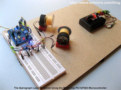
The principle of making the spirograph laser projector is to use at least two DC motors with the attached mirror on it, these mirrors then will deflect the laser beam from one DC motor mirror to the second DC motor mirror and then finally to the screen. By controlling each of the DC motors spinning speed we could generate a fascinating laser spirograph pattern on the screen as shown on this following picture.

The best way to control the DC motor speed is to use the PWM (pulse wave modulation) signal to drive the DC Motor and because we want to change the DC motor speed manually, therefore we need to use the trimport or potentiometer to control each of the DC motors speed. Hmm, this sound like an appropriate job for the microcontroller but could we use this tiny 8 pins PIC12F683 microcontroller to handle this task?

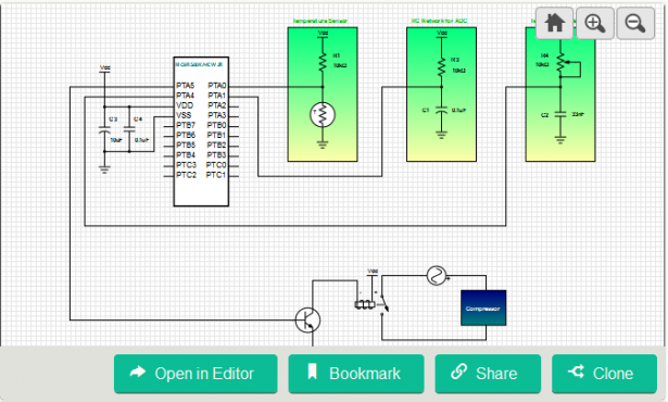
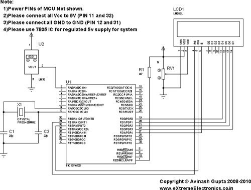
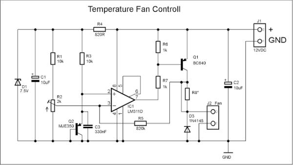
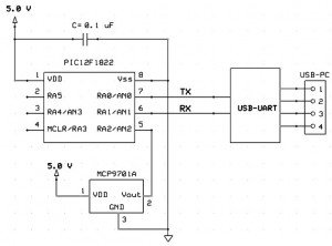
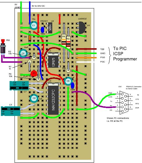
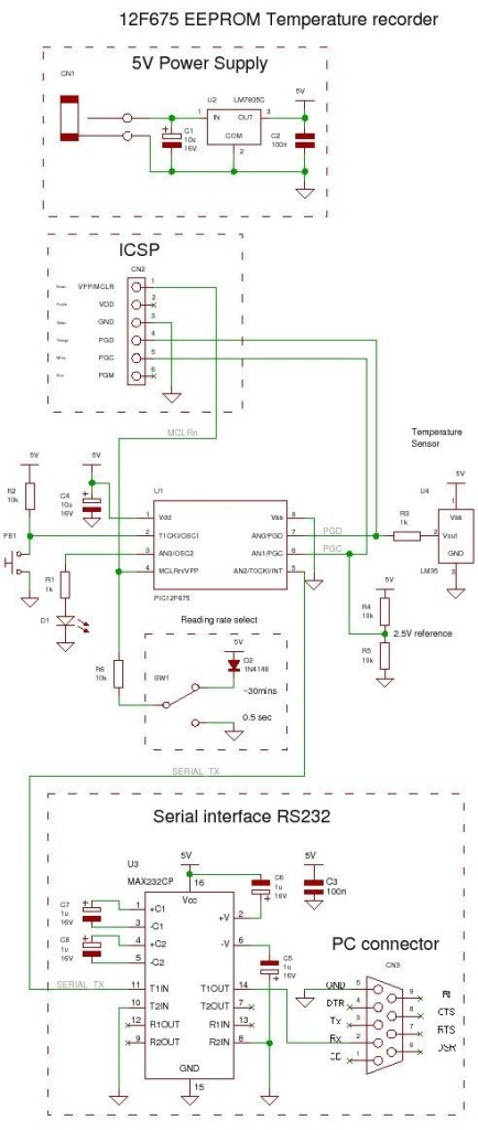
From the datasheet you will notice that the Microchip PIC12F683 microcontroller only has one PWM output (CCP1) and four ADC input channel (AN0, AN1, AN2 and AN3). Because we need two PWM output, therefore instead of using the PIC12F683 microcontroller build in PWM peripheral, in this tutorial I will show you how to generate the PWM signal base on the PIC12F683 microcontroller TIMER0 peripheral. The following is the complete electronic schematic for the laser projector project.

Ok before we go further with the detail; let’s list down the supporting peripherals needed to complete this laser projector project:

  • Hot glue gun
  • Keychain laser pointer or any available laser pointer
  • 3xAA, 4.5 volt battery holder for powering the laser pointer, please use the same voltage rate used by your laser pointer.
  • Two DC motor taken from the discarded PS2 Dual shock joystick
  • Two toy’s car tire taken from tamiya racing car
  • CD/DVD for the mirror, use a kitchen scissor to cut the CD/DVD into the two circle shape mirror with approximately 38 mm in diameter
  • Some toys plastic bricks for holding the DC motor
  • Breadboard
  • Hardboard or acrylic is used for the base of our laser projector
  • Double Tape

The following are the electronic parts and the software development tools that I used to make this laser projector project:

  • Resistor: 330 (3), 1K (5) and 10K (1)
  • Trimport: 10K (2)
  • Capacitor: 100nF (2) and 10nF (1)
  • One 100uH Inductor
  • Two 1N4148 Diodes
  • Two Blue and one Red Light Emitting Diode (LED)
  • Two 2N2222A transistors
  • One Mini Push Button Switch
  • One Microchip PIC12F683 Microcontroller
  • Microchip MPLAB v8.46 IDE (Integrated Development Environment)
  • Microchip Macro Assembler MPASMWIN.exe v5.35, mplink.exe v4.35
  • HI-TECH C Compiler for PIC10/12/16 MCUs (Lite Mode) V9.70
  • Microchip PICKit3 Programmer (Firmware Suite Version: 01.25.20)

This project is aim as the continuing lessons to my previous posted blog Introduction to PIC Assembly Language Part-1 and Introduction to PIC Assembly Language Part-2, therefore I used the same PIC12F683 board presented in the part 2 which you could down load both of the electronic schematic and the PCB layout designed in Eagle CAD format. The other interesting feature of this laser projector project is; besides the PIC assembly code I also provide the C language version of this project for the C language lover and is compiled with the HI-TECH C Compiler (recently the HI-TECH Software has been acquired by Microchip). This C language version could be used for learning as well as the embedded system programming language comparison.

In this project I also use a new Microchip PICKit3 programmer but of course you could use the Microchip PICKit2 programmer to download the hex code to the PIC12F683 microcontroller flash.

Building your own Simple Laser Projector using the Microchip PIC12F683

The following is the Laser Projector code in PIC Assembly Language:

;******************************************************************************
;  File Name    : laserlight.asm
;  Version      : 1.0
;  Description  : Laser Light Show Project
;  Author       : RWB
;  Target       : Microchip PIC12F683 Microcontroller
;  Compiler     : Microchip Assembler (MPASMWIN.exe v5.35, mplink.exe v4.35)
;  IDE          : Microchip MPLAB IDE v8.46
;  Programmer   : PICKit3 (Firmware Suite Version: 01.25.20)
;  Last Updated : 01 April 2010
; *****************************************************************************
#include <p12F683.inc>
__config (_INTRC_OSC_NOCLKOUT & _WDT_OFF & _PWRTE_OFF & _MCLRE_OFF & _CP_OFF & _IESO_OFF & _FCMEN_OFF)
#define MAX_TMR0 0xFB
#define MAX_COUNT .200
#define MAX_DEBOUNCE 0x0A
#define MAX_TBLINDEX 0x0A
; Define variables used
     cblock 0x20
Delay:2                      ; Define two registers for the Delay and Delay + 1
mode                         ; Operation Mode
pwm_count                    ; Hold the Main PWM Counter
pwm_m1                       ; Hold the PWM width for Motor 1
pwm_m2                       ; Hold the PWM width for Motor 2
keycount                     ; Debounce Count
tableindex                   ; Table Index for Auto PWM
     endc
; Define variable use for storing STATUS and WREG register
     cblock 0x70             ; Use unbanked RAM, available both in Bank0 and Bank1
saved_w
saved_status
     endc
; Start the Light show Assembler Code here
     org 0x00                ; We always start at flash address 0
     goto Main               ; Jump to Main
     org 0x04                ; 0x04: Start PIC Interrupt Address
PIC_ISR:                     ; Start the PIC Interrupt Service Routine
     movwf   saved_w         ; Save Working Register
     movf    STATUS,w        ; Save Status Register
     movwf   saved_status
; Check the TIMER0 Interrupt here
     btfss   INTCON,T0IF
     goto    ExitISR         ; If (T0IF != 1) then Exit ISR
     bcf     STATUS,RP0      ; Select Registers at Bank 0
     incf    pwm_count       ; pwm_count++
     movlw   MAX_COUNT
     subwf   pwm_count,w     ; if (pwm_count < MAX_COUNT) then CheckPWM
     btfss   STATUS,C        ; else clear GP1 and GP2
     goto    CheckPWM
     bcf     GPIO,GP1        ; GPIO1=0
     bcf     GPIO,GP2        ; GPIO2=0
     goto    ExitPWM
CheckPWM:
     movf    pwm_m1,w
     subwf   pwm_count,w
     btfsc   STATUS,Z        ; if (pwm_count == pwm_m1) then Set GP1
     bsf     GPIO,GP1        ; Set GP1 Bit
CheckM2:
     movf    pwm_m2,w
     subwf   pwm_count,w
     btfsc   STATUS,Z        ; if (pwm_count == pwm_m2) then Set GP2
     bsf     GPIO,GP2        ; Set GP2 bit
ExitPWM:
     bcf     INTCON,T0IF     ; clear the TIMER0 interrupt flag
     movlw   MAX_TMR0
     movwf   TMR0            ; TMR0 = MAX_TMR0
ExitISR:
     movf    saved_status,w
     movwf   STATUS          ; Restore STATUS Register
     swapf   saved_w,f
     swapf   saved_w,w       ; Restore W Register
     retfie                  ; Return from Interrupt
Main:
     bsf     STATUS,RP0      ; Select Registers at Bank 1
     movlw   0x70
     movwf   OSCCON          ; Set the internal clock speed to 8 MHz
     movlw   0x39            ; GP1 and GP2 Output, GP0,GP3,GP4 and GP5 as Input
     movwf   TRISIO          ; TRISIO = 0x39        

     bcf     STATUS,RP0      ; Select Registers at Bank 0
     movlw   0x07
     movwf   CMCON0          ; Turn off Comparator (GP0, GP1, GP2)
     clrf    GPIO

; Now we Set the ADC Peripheral
     bsf     STATUS,RP0      ; Select Registers at Bank 1
     movlw   0x79            ; Set AN0 (GP0) and AN3 (GP4) as Analog Input
     movwf   ANSEL           ; Using the Internal Clock (FRC)  

; Now we set the TIMER0 Peripheral
; TIMER0 Period = 1/FSOC x 4 x Prescale x TMR0
     movlw   0x00            ; Use TIMER0 Prescaler 1:2, Internal Clock
     movwf   OPTION_REG      ; OPTION_REG = 0x00
     bcf     STATUS,RP0      ; Select Registers at Bank 0
     movlw   MAX_TMR0
     movwf   TMR0            ; TMR0=MAX_TMR0      

; Initial the variables used
     clrf    mode            ; Default mode = 0, Light Show Off
     clrf    pwm_count       ; pwm_count = 0
     clrf    pwm_m1          ; pwm_m1 = 0
     clrf    pwm_m2          ; pwm_m2 = 0
     clrf    keycount        ; keycount = 0
     clrf    tableindex      ; tableindex = 0
; Activate the Interrupt
     bsf     INTCON,GIE      ; Enable Global Interrupt
MainLoop:
     btfsc   GPIO,GP5        ; Now we check the Button
     goto    CheckMode       ; if (GP5 != 0) goto CheckMode
     movlw   0x01
     addwf   keycount        ; keycount=keycount + 1
     movf    keycount,w
     sublw   MAX_DEBOUNCE
     btfss   STATUS,C        ; if (keycount > MAX_DEBOUNCE) goto KeyPressed
     goto    KeyPressed
     goto    CheckMode       ; else CheckMode
KeyPressed:
     clrf    keycount        ; keycount=0
     incf    mode            ; mode++
     movlw   0x03
     subwf   mode,w          ; W = mode - 0x03
     btfsc   STATUS,C        ; if (mode >= 0x03)
     clrf    mode            ; mode=0;
     movlw   0x01            ; else check the mode
     subwf   mode,w
     btfss   STATUS,C        ; if (mode >= 0x01) goto TurnOn
     goto    TurnOff         ; else goto TurnOff
     goto    TurnOn
TurnOff:
     bcf     INTCON,T0IE     ; Disable TIMER0 Interrupt
     clrf    pwm_count       ; pwm_count = 0
     clrf    pwm_m1          ; pwm_m1 = 0
     clrf    pwm_m2          ; pwm_m2 = 0
     bcf     GPIO,GP1
     bcf     GPIO,GP2
     movlw   .250
     call    DelayMs         ; DelayMs(250)
     movlw   .250
     call    DelayMs         ; DelayMs(250)
     goto    CheckMode
TurnOn:
     bsf     INTCON,T0IE     ; Enable TIMER0 Interrupt                    

CheckMode:
     movlw   0x01
     subwf   mode,w
     btfss   STATUS,Z        ; if (mode == 1) goto ShowMode1
     goto    CheckMode2
     goto    ShowMode1
CheckMode2:
     movlw   0x02
     subwf   mode,w
     btfss   STATUS,Z        ; if (mode == 2) goto ShowMode2
     goto    KeepLoop
     goto    ShowMode2
ShowMode1:                   ; Used ADC for PWM
     movlw   B'00000001'     ; Left Justify and turn on the ADC peripheral, channel 0 (AN0)
     movwf   ADCON0          ; Vreff=Vdd
     bsf     ADCON0,GO       ; Start the ADC Conversion on channel 0 (AN0)
     btfss   ADCON0,GO       ; while(GO == 1)
     goto    $-1             ; Keep Loop
     call    Delay1ms
     movlw   B'00000001'     ; Left Justify and turn on the ADC peripheral, channel 0 (AN0)
     movwf   ADCON0          ; Vreff=Vdd
     bsf     ADCON0,GO       ; Start the ADC Conversion on channel 0 (AN0)
     btfss   ADCON0,GO       ; while(GO == 1)
     goto    $-1             ; Keep Loop
     movf    ADRESH,w        ; Conversion Done, Read ADRESH
     movwf   pwm_m1          ; pwm_m1 = ADRESH
     call    Delay1ms

     movlw   B'00001101'     ; Left Justify and turn on the ADC peripheral, channel 3 (AN3)
     movwf   ADCON0          ; Vreff=Vdd
     bsf     ADCON0,GO       ; Start the ADC Conversion on channel 3 (AN3)
     btfss   ADCON0,GO       ; while(GO == 1)
     goto    $-1             ; Keep Test
     call    Delay1ms
     movlw   B'00001101'     ; Left Justify and turn on the ADC peripheral, channel 3 (AN3)
     movwf   ADCON0          ; Vreff=Vdd
     bsf     ADCON0,GO       ; Start the ADC Conversion on channel 3 (AN3)
     btfss   ADCON0,GO       ; while(GO == 1)
     goto    $-1             ; Keep Test
     movf    ADRESH,w        ; Conversion Done, Read ADRESH
     movwf   pwm_m2          ; pwm_m2 = ADRESH
     call    Delay1ms
     goto    KeepLoop
ShowMode2:                   ; Used Predefined Value for PWM
     movf    tableindex,w
     call    tablepwm1       ; Call tablepwm1
     movwf   pwm_m1          ; Assigned it to pwm_m1
     movlw   .30
     call    DelayMs         ; DelayMs(30)

     movf    tableindex,w
     call    tablepwm2       ; Call tablepwm2
     movwf   pwm_m2          ; Assigned it to pwm_m2
     movlw   .30
     call    DelayMs         ; DelayMs(30)
     incf    tableindex      ; tableindex++
     movlw   MAX_TBLINDEX
     subwf   tableindex,w
     btfss   STATUS,C        ; if (tableindex >= 0x0A) then tableindex = 0
     goto    KeepLoop
     clrf    tableindex      ; tableindex = 0
KeepLoop:
     goto    MainLoop        ; Goto MainLoop
; Predefined value table for Automatic PWM
tablepwm1:
     addwf   PCL,f
     retlw   0x10
     retlw   0x5A
     retlw   0x9A
     retlw   0x20
     retlw   0x40
     retlw   0x8A
     retlw   0x82
     retlw   0x30
     retlw   0x58
     retlw   0xAA
tablepwm2:
     addwf   PCL,f
     retlw   0x70
     retlw   0x8A
     retlw   0x2A
     retlw   0x30
     retlw   0x1C
     retlw   0x2A
     retlw   0x4B
     retlw   0xA0
     retlw   0x18
     retlw   0x2A
;----------------- DelayMs: Millisecond Delay Subroutine ----------------------
; Paramater: WREG = delay amount in milisecond, max: 255 millisecond
DelayMs:
     movwf   Delay + 1
DelayLoop:
     call    Delay1ms
     decfsz  Delay + 1,f     ; Decrease Delay + 1, If zero skip the next instruction
     goto    DelayLoop       ; Not zero goto DelayLoop
     return                  ; return to the caller
;----------------- Delay1ms: 1 ms Delay Subroutine ---------------------------
Delay1ms:                    ; Total Delay: 1998 x 0.5us ~ 1 ms
     movlw   0x99
     movwf   Delay
DelayLoop1:
     decfsz  Delay,f         ; Decrease Delay, If zero skip the next instruction
     goto    DelayLoop1
DelayLoop2:
     decfsz  Delay,f         ; Decrease Delay, If zero skip the next instruction
     goto    DelayLoop2      ; Not zero goto DelayLoop2
DelayLoop3:
     decfsz  Delay,f         ; Decrease Delay, If zero skip the next instruction
     goto    DelayLoop3      ; Not zero goto DelayLoop2
     return                  ; Return to the caller
     end
; EOF: laserlight.asm

The following is the Laser Projector Project code in C Language version:

// ***************************************************************************
//  File Name    : laserlight.c
//  Version      : 1.0
//  Description  : Laser Light Show Project
//  Author       : RWB
//  Target       : Microchip PIC12F683 Microcontroller
//  Compiler     : HI-TECH C PIC10/12/16 MCUs (Lite Mode) V9.70
//  IDE          : Microchip MPLAB IDE v8.46
//  Programmer   : PICKit3 (Firmware Suite Version: 01.25.20)
//  Last Updated : 03 April 2010
// ***************************************************************************
#include <pic.h>
/*   PIC Configuration Bit:
**   INTIO     - Using Internal RC No Clock
**   WDTDIS    - Wacthdog Timer Disable
**   PWRTEN    - Power Up Timer Enable
**   MCLRDIS   - Master Clear Disable
**   UNPROTECT - Code Un-Protect
**   UNPROTECT - Data EEPROM Read Un-Protect
**   BORDIS    - Borwn Out Detect Disable
**   IESODIS   - Internal External Switch Over Mode Disable
**   FCMDIS    - Monitor Clock Fail Safe Disable
*/
__CONFIG(INTIO & WDTDIS & PWRTEN & MCLRDIS & UNPROTECT \
  & UNPROTECT & BORDIS & IESODIS & FCMDIS);
// Using Internal Clock of 8 MHz
#define FOSC 8000000L
#define MAX_COUNT 200
#define MAX_TMR0 0xFB
#define MAX_DEBOUNCE 0x0A
#define MAX_TBLINDEX 0x0A
unsigned char pwm_count=0;
unsigned char pwm_m1=0;
unsigned char pwm_m2=0;
unsigned char tablepwm1[10]={0x10,0x5A,0x9A,0x20,0x40,0x8A,0x82,0x30,0x58,0xAA};
unsigned char tablepwm2[10]={0x70,0x8A,0x2A,0x30,0x1C,0x2A,0x4B,0xA0,0x18,0x2A};
unsigned char tableindex=0;
/* The Delay Function */
#define	delay_us(x) { unsigned char us; \
			        us = (x)/(12000000/FOSC)|1; \
			        while(--us != 0) continue; }
void delay_ms(unsigned int ms)
{
  unsigned char i;
  do {
    i = 4;
    do {
      delay_us(164);
    } while(--i);
  } while(--ms);
}
static void interrupt isr(void)
{
  if(T0IF) {	       // TIMER0 Interrupt Flag
    pwm_count++;       // PWM Count Increment
    if (pwm_count >= MAX_COUNT) {
      pwm_count=0;
      GPIO1=0;         // Turn off GP1
      GPIO2=0;         // Turn off GP2
    }
    if (pwm_count == pwm_m1) {
      GPIO1=1;         // Turn On GP1
    }    

    if (pwm_count == pwm_m2) {
      GPIO2=1;         // Turn On GP2
    }      

    TMR0 = MAX_TMR0;   // Initial Value for TIMER0 Interrupt
    T0IF = 0;	       // Clear TIMER0 interrupt flag
  }
}
void main(void)
{
  unsigned char mode,keycount;
  OSCCON=0x70;         // Select 8 MHz internal clock
  /* Initial Port Used */
  TRISIO = 0x39;       // GP1 and GP2 Output, GP0,GP3,GP4 and GP5 as Input
  CMCON0 = 0x07;       // Turn off Comparator (GP0, GP1, GP2)
  GPIO = 0x00;         // Turn Off all IO
  /* Init ADC Peripheral */
  ANSEL = 0x79;        // Set AN0 (GP0) and AN3 (GP4) as Analog Input, Internal Clock
  /* Init TIMER0: TIMER0 Period = 1/FSOC x 4 x Prescale x TMR0*/
  OPTION = 0b00000000; // 1:2 Prescale
  TMR0=MAX_TMR0 ;
  /* Init Variable Used */
  pwm_count=0;
  pwm_m1=0;
  pwm_m2=0;
  mode=0;
  keycount=0;
  tableindex=0;
  GIE =1;		       // Enable Global Interrupt

  for(;;) {
    // Display the LED
    if (GPIO5 == 0) {
      keycount++;
      if (keycount > MAX_DEBOUNCE) {
        keycount=0;
        mode = mode + 1;
        if (mode > 2) mode = 0;
        if (mode >= 0x01) {
          T0IE = 1;	       // Enable TIMER0 Interrupt on Overflow
        } else {
          T0IE = 0;	       // Disable TIMER0 Intterupt on Overflow
          pwm_count=0;
          pwm_m1=0;
          pwm_m2=0;
          GPIO1=0;             // Turn off GP1
          GPIO2=0;             // Turn off GP2
          delay_ms(500);
        }
      }
    }
    if (mode == 1) {
      /* Read the ADC here */
      ADCON0=0b00000001;       // select left justify result. ADC port channel AN0
      GODONE=1;	               // initiate conversion on the channel 0
      while(GODONE) continue;  // Wait for ldr_left conversion done
      pwm_m1=ADRESH;           // Read 8 bits MSB, Ignore 2 bits LSB in ADRESL
      delay_ms(1);
      /* Read the ADC here */
      ADCON0=0b00001101;       // select left justify result. ADC port channel AN3
      GODONE=1;	         // initiate conversion on the channel 4
      while(GODONE) continue;  // Wait for ldr_left conversion done
      pwm_m2=ADRESH;           // Read 8 bits MSB, Ignore 2 bits LSB in ADRESL     

      delay_ms(1);
    }
    if (mode == 2) {
      pwm_m1=tablepwm1[tableindex];
      delay_ms(10);
      pwm_m2=tablepwm2[tableindex];
      delay_ms(10);
      tableindex++;
      if (tableindex >= MAX_TBLINDEX)
        tableindex = 0;
    }
  }
}
/* EOF: laserlight.c */

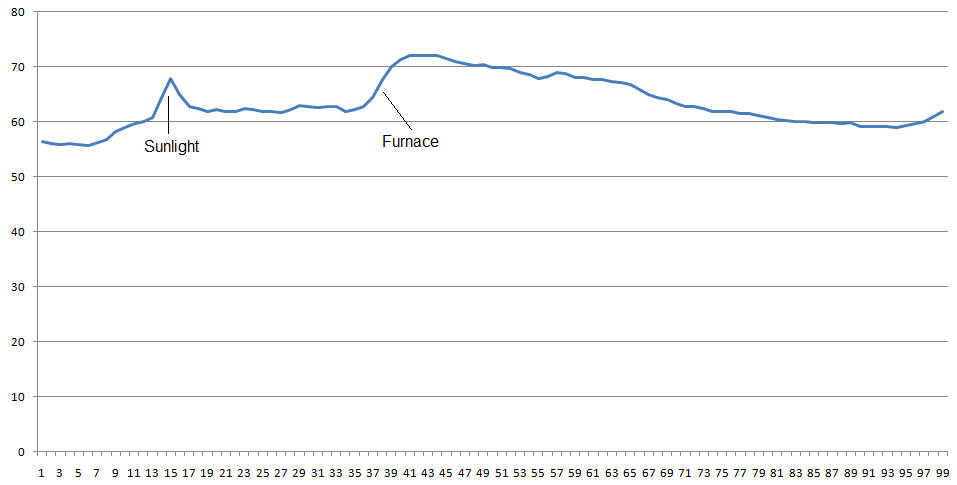
Generating the PWM (Pulse Width Modulation)


For more detail: Building your own Simple Laser Projector using the Microchip PIC12F683 Microcontroller

The post Building your own Simple Laser Projector using the Microchip PIC12F683 Microcontroller appeared first on PIC Microcontroller.

Viewing all 365 articles
Browse latest View live


<script src="https://jsc.adskeeper.com/r/s/rssing.com.1596347.js" async> </script>