Quantcast
Channel: temperature | Battery Guide
Viewing all 365 articles
Browse latest View live

DC Motor Control using Temperature Sensor & 8051 Microcontroller

$
0
0

Microcontroller are widely used in electronics gadget and are one of the key element in developing any project and thus this project used 8051 microcontroller and will help in teaching about interfacing of temperature sensor with ATMEL microcontroller by means of ADC, to display the temperature on a 16×2 LCD and to rotate a DC motor at two different speeds at various temperatures. This project on digital thermometer is good implementation of project using microcontroller. DC Motor Control using Temperature Sensor & 8051 Microcontroller

In this project, we have now given a new temperature feedback to your temperature sensor which in turn modifications this to your similar a new analog voltage which is to be directed at a ADC. For you to convert this analog files in to a digital waveform, determined by a new reference voltage and that is fed to your microcontroller this temperature are going to be viewable with a 16×2 LCD. Control of DC motor is done in such a way that it runs on two different speed depending upon the temperature.
For implementation of this project Proteus software is used which is a software for microcontroller simulation, schematic capture and printed circuit board design and is developed by Labcenter electronics.DC Motor Control using Temperature Sensor & 8051 Microcontroller schematic

This project report contains the circuit diagram and its analysis along with the microcontroller programming for help. In this project LCD and ADC0804 interfacing with AtmelAT89C51 was studied and implemented on Proteus and same was assembled on a PCB. Thus we have successfully made a dc motor to run at different speeds by varying temperature. You can use this project for your reference and study work.


For more detail: DC Motor Control using Temperature Sensor & 8051 Microcontroller

The post DC Motor Control using Temperature Sensor & 8051 Microcontroller appeared first on PIC Microcontroller.


Non-Contact Body Temperature Meter

$
0
0

One of the most commonly used medical instruments nowadays is the thermometer. The thermometer is used to monitor or measure the body temperature of a sick person. The idea of creating a thermometer started from a device called thermoscope, a thermometer without a scale. Several inventors developed it until Sir Thomas Allbutt invented the first practical 6-inch medical thermometer able to sense a body temperature in five minutes. The development of the thermometer did not stop there and today, digital thermometer exists which is faster and very accurate.

Non-Contact Body Temperature Meter

This reference design is an example of a low cost non-contact digital thermometer. It only uses a microcontroller, a four digit seven segment display and an infrared (IR) temperature sensor. The concept of this design is to make the IR sensor measure the temperature of the thermal radiation emitted by the body being measured. The data acquired by the sensor will be sent to the microcontroller through the I2C bus. The microcontroller will analyze the data and then shows the body temperature on the four-digit seven-segment display.

The circuit of this reference design uses few components only and is very easy to understand. However, to make the circuit function accurately, software calibration must be implemented carefully. The whole circuit is powered by a 5V DC power supply regulated from the four 20mm coin shape batteries contained in a 120591-1 TE Connectivity battery holder. The batteries are connected in series-parallel connection to produce a 6V 480mAh source of power. With the help of a low-dropout voltage regulator, the 6V is regulated to a 5V DC supply.

For more detail:   Non-Contact Body Temperature Meter


The post Non-Contact Body Temperature Meter appeared first on PIC Microcontroller.

StickOS and CPUStick – Build a Simple Toaster Oven Temperature Profile Controller 2/2

$
0
0

Using a highly-integrated microcontroller running “StickOS BASIC”, it is possible to quickly build a toaster oven temperature profile controller for performing surface mount (SMT) printed circuit board reflow soldering at home. Continuing with the first article, the schematic and configuration for the Toaster Oven Temperature Profile are presented.


1. Schematic and configuration

The schematic for the Toaster Oven Temperature Profile Controller is shown in Figure 1.

Once the Toaster Oven Temperature Profile Controller is built, the next step is to install StickOS BASIC on the UBW32 Board. This is achieved as follows:

1. Hold down the PRG switch on the UBW32 and connect the UBW32 to the host computer USB port; you should see alternating blinking white and green LEDs indicating the UBW32 is ready to download a firmware file.

2. Run the HIDBootLoader.exe application from the zip archive on the UBW32 homepage: http://www.schmalzhaus.com/UBW32/.

3. Click “Open Hex File” and browse to StickOS.UBW32.v1.50g.elf.hex.

4. Click “Program/Verify”

5. Press the reset switch on the UBW32 to start StickOS running:you should see a slowly blinking orange LED indicating StickOS is idle (this LED will blink quickly when StickOS is running a BASIC program). The next step is to install the USB Virtual COM Port driver on the USB host computer, if it is not there already. When the MCU is connected to a USB host computer, it will present an FTDI Serial Port function to the host computer. An appropriate signed driver will be loaded automatically from microsoft.com, if needed (and if you are connected to the Internet), or you can manually install the VCP driver from http://www.ftdichip.com/FTDrivers.htm. Once the driver is loaded, a new virtual COM port (VCP) will be present on your system. The virtual COM port will be visible in

For more detail:  StickOS and CPUStick – Build a Simple Toaster Oven Temperature Profile Controller 2/2

The post StickOS and CPUStick – Build a Simple Toaster Oven Temperature Profile Controller 2/2 appeared first on PIC Microcontroller.

HDC1050 Low Power, High Accuracy Digital Humidity Sensor with Temperature Sensor (Rev. C)

$
0
0

1 Features

  • Relative Humidity Accuracy ±3% (typical)
  • Temperature Accuracy ±0.2°C (typical)
  • 14 Bit Measurement Resolution
  • 100 nA Sleep Mode Current
  • Average Supply Current:
    • 710 nA @ 1sps, 11 bit RH Measurement
    • 1.3 µA @ 1sps, 11 bit RH and Temperature Measurement
  • Supply Voltage 2.7 V to 5.5 V
  • Small 3 mm x 3 mm Device Footprint
  • I2C Interface
    HDC1050 Low Power, High Accuracy Digital Humidity Sensor with Temperature Sensor

2 Applications

  • HVAC
  • Smart Thermostats and Room Monitors
  • White Goods
  • Printers
  • Handheld Meters
  • Medical Devices
  • Wireless Sensor (TIDA-00374)

3 Description

The HDC1050 is a digital humidity sensor with integrated temperature sensor that provides excellent measurement accuracy at very low power. The HDC1050 operates over a wide supply range, and is a low cost, low power alternative to competitive solutions in a wide range of common applications. The humidity and temperature sensors are factory calibrated.

Device Information (1)

PART NUMBER PACKAGE BODY SIZE (NOM)
HDC1050 PWSON (6-pin) DMB 3.00 mm x 3.00 mm
  1. For all available packages, see the orderable addendum at the end of the datasheet.

4 Typical Application

Copyright© 2015, Texas Instruments Incorporated. An IMPORTANT NOTICE at the end of this data sheet addresses availability, warranty, changes, use in safety-critical applications, intellectual property matters and other important disclaimers.

Submit Documentation Feedback

For more detail:  HDC1050 Low Power, High Accuracy Digital Humidity Sensor with Temperature Sensor (Rev. C)

The post HDC1050 Low Power, High Accuracy Digital Humidity Sensor with Temperature Sensor (Rev. C) appeared first on PIC Microcontroller.

Howto Measure RTD (Resistance Temperature Detectors) over long distances

$
0
0

There is a multitude of process parameters nowadays that need to be measured in the industrial environment (temperature, pressure, humidity, force etc.). Out of these, undoubtedly the most common one is temperature, as it influences most manufacturing parameters. It is no wonder then that many solutions have been developed over time to measure it. There are a few general categories any industrial temperature sensor will fall into: thermocouples, RTDs (Resistance Temperature Detectors), thermistors and integrated silicon sensors. There is no “best sensor” rather they all have pros and cons which need to be individually evaluated for each application.

Howto Measure RTD (Resistance Temperature Detectors) over long distances

1. Introduction

The RTDs are the most expensive, but they also provide best accuracy and best resolution for the measurement. This, however, only if appropriate analogue circuitry will be used (which of course will add cost to the already high price of the sensor itself). The appropriate analogue circuitry constitutes the subject of this article. RTDs are regarded as the best quality temperature sensors (when it is worth paying for them). They provide accurate and stable measurements over time, and, most important, they provide a linear resistance-temperature characteristic. In the figure 1 is shown the resistance-temperature characteristic of the most common RTD, the PT100, which gives 100Ohms at a temperature of 0 Celsius degrees.

For more detail:  Howto Measure RTD (Resistance Temperature Detectors) over long distances

The post Howto Measure RTD (Resistance Temperature Detectors) over long distances appeared first on PIC Microcontroller.

High-temperature versions of MEC switches now for the price of standard versions.

$
0
0

ompany MEC, Dutch producer of top-class push-button switches Multimec, Unimec and others comes with good news for developers and producers of electronics.

Well-known reliable push-buttons were in majority of cases available in so called standard version (L6, -40…+115°C) and in a high-temperature version (H9, -40…+160°C).

High-temperature versions of MEC switches now for the price of standard versions. From now on, all types will be gradually available only in a „high temperature“ version, which can be identified by „H9“marking in suffix. This applies to Multimec 3 and Unimec series (series Multimec 5 is already from the beginning only available in a high-temperature version).

The main „good news“ is, that these high-temperature types will be available for practically identical prices like standard types. That´s why, even in applications where you wouldn´t necessarily need that high thermal resistance, you can use this high-temp version and profit from unchanged price and potentially wider possibilities of usage of your product.

The most suitable type for you application can be easily found in the MEC catalogue (11MB).


For more detail: High-temperature versions of MEC switches now for the price of standard versions. 

The post High-temperature versions of MEC switches now for the price of standard versions. appeared first on PIC Microcontroller.

Simplest Temperature Data Logger using PIC12F683

$
0
0

Introduction
There are varieties of digital temperature logger projects available online based on different microcontrollers. The one I am going to talk about is based on a Microchip’s 8-pin microcontroller, PIC12F683. It reads temperature values from a DS1820 digital sensor and stores in its internal EEPROM. PIC12F683 has 256 bytes of internal EEPROM and we are going to store the temperature values in 8-bit format. This means only the eight most significant bits of temperature data from DS1820 will be read and as such the temperature resolution will be of 1 degree C.

Logger

My temperature logger has following features:

  • Reads temperature from a DS1820 sensor and stores in the internal EEPROM locations.
  • Can store up to 254 temperature values. EEPROM location 0 is used to store the sampling interval, and location 1 is used to store the number of records.
  • Three sampling interval options: 1 sec, 1 min, and 10 min. This can be selected during powering up.
  • Start and Stop buttons for control operations.
  • The recorded temperature values can be sent to PC through a serial port. A separate Send button is available to initiate data transfer.
  • A LED to indicate various ongoing operations.
  • Reset button to clear all previous records.


Circuit Design
PIC12F683 has 6 I/O pins, out of which one (GP3, pin 4) is I/P only pin. Here is how we are going to assign the port pins.
The six I/O pins of PIC12F683 are assigned as follows:
1. GP0 (Pin 7, I/P): This pin will be used to read the temperature value from DS1820 sensor.
2. GP1 (Pin 6, O/P): This will be used for serial data transfer to a PC.
3. GP2 (Pin 5, O/P): LED output pin.
4. GP3 (Pin 4, I/P): Send (tactile switch)
5. GP4 (Pin 3, I/P): Stop (tactile switch)
6. GP5 (Pin 2, I/P): Start (tactile switch)

Current Project / Post can also be found using:

  • how to measure temperature with pic and micro c with data logger
  • Digital clock with automatic alarm and temperature monitor using pic pdf
  • project on temperature measuring instrument

The post Simplest Temperature Data Logger using PIC12F683 appeared first on PIC Microcontroller.

Lithium-Ion Battery Warms Up, Operates In Subzero Temperatures

$
0
0

A new “all-climate” lithium-ion battery can rapidly heat itself to overcome freezing temperatures with little sacrifice in energy storage capacity and power, researchers say.

This advance might enable applications for which high-performance batteries are needed in extremely cold temperatures, such as electric cars in cold climates, high-altitude drones, and space exploration. EC Power is now creating all-climate battery cells in pilot-production volumes that can be put directly in vehicles, says study lead author Chao-Yang Wang, a mechanical and electrochemical engineer at Pennsylvania State University.

Lithium-Ion Battery Warms Up, Operates In Subzero Temperatures

Lithium-ion batteries not only can suffer problems from overheating, but they also typically experience severe power loss at temperatures below zero degrees Celsius. The consequences of this weakness include slow charging in cold weather, limited regenerative braking, the need for larger, more expensive battery packs to start cold engines, and the reduction of vehicle cruise range by as much as 40 percent, researchers say.

Previous attempts to help lithium-ion batteries perform better at low temperatures have considered additives to the electrolytes that connect the electrodes of batteries. However, such additives can release gases at high temperatures that reduce battery life. Another strategy to keep batteries working in the cold involves externally insulating and heating the batteries, but external insulation and heaters make batteries larger and heavier, which is unwelcome in such applications as high-altitude drones where space and weight are concerns.

Now researchers have developed what they call an all-climate lithium-ion battery that can heat itself up from below freezing without the need for electrolyte additives or external heating devices.

The new device adds a 50-micrometer-wide sheet of nickel foil to its interior. This design allows the battery to divert electrical current through the foil at freezing temperatures to produce heat with about 90 percent energy efficiency. Once this heating effect raises the internal temperature of the battery above freezing, a switch is triggered, and the battery reverts to normal operations.

“A thin nickel foil ends the era of batteries not working at low temperatures,” Wang says. “Our project has been a multi-year effort and we went through many sophisticated ideas and synthesis techniques, but at the end we were surprised that a thin nickel foil works so well and involves minimal alterations.”

The prototype was capable of warming from -20 to zero degrees Celsius in roughly 20 seconds and -30 to zero degrees Celsius in roughly 30 seconds while consuming only 3.8 and 5.5 percent of its energy storage capacity, respectively. Such heating could help this all-climate battery provide much more usable energy, and much longer cruising ranges for electric cars, than standard lithium-ion batteries in extreme cold, the researchers say.

For instance, the researchers calculated their battery could provide 102 watt-hours per kilogram at -40° C, whereas batteries without the nickel foil could only yield 0.3 watt-hours per kilogram at that temperature. Similarly, they note their battery could five to six times more power at -30° C than batteries without the nickel foil.

For more detail:   Lithium-Ion Battery Warms Up, Operates In Subzero Temperatures

The post Lithium-Ion Battery Warms Up, Operates In Subzero Temperatures appeared first on PIC Microcontroller.


Humidity and temperature measurements with Sensirion’s SHT1x/SHT7x sensors using PIC18F2550 (Part 1)

$
0
0

Temperature and relative humidity are two very important ambient parameters that are directly related to human comfort. Sometimes, you may be able to bear higher temperatures, if there is a lower relative humidity, such as in hot and dry desert-like environment. However, being in a humid place with not very high temperature may make you feel like melting. This is because if there is high relative humidity, sweat from our body will evaporate less into the air and we feel much hotter than the actual temperature. Humidifiers and dehumidifiers help to keep indoor humidity at a comfortable level. Today we will discuss about Sensirion’s SHT series of digital sensors, more specifically SHT11 and SHT75, which are capable of measuring both temperature and relative humidity and provide fully calibrated digital outputs. We will interface both the sensors to PIC18F2550 microcontroller and compare the two sets of  measurements to see the consistency between the two sensors. This tutorial is divided into two parts. The first part will cover all the details regarding the sensors, including their specification, interface, and communication protocol. The second part will be more focussed on the circuit diagram, implementation of the communication protocol with PICMicro, and the results.

Sensirion’s SHT1x

Theory

Sensirion offers multiple SHT series of digital sensors for measuring both relative humidity and temperature. The temperature is measured using a band-gap sensor, whereas the humidity sensor is capacitive; which means the presence of moisture in air changes the dielectric constant of the material in between the two plates of a parallel-plate capacitor, and hence varies the capacitance. The required signal conditioning, analog-to-digital conversion, and digital interface circuitries are all integrated onto the sensor chip. The various SHT series sensors have different levels of accuracy for humidity and temperature measurements, as described below.

SHT1x, 2x, and 7x series of humidity sensors (Source: http://www.sensirion.com)

SHT1x are available in surface mount type whereas SHT7x are supplied with four pins which allows easy connection. The SHT11 and SHT75 sensors both provide fully calibrated digital outputs that can be read through a two-wire (SDA for data and SCK for clock) serial interface which looks like I2C but actually it is not compatible with I2C. An external pull-up resistor is required to pull the signal high on the SDA line. However, the SCK line could be driven without any pull-up resistor. The signaling detail of the serial bus is described in the datasheet, which we will implement for PIC18F2550 microcontroller using mikroC pro for PIC compiler. The operating range of both the sensors is 0 to 100% for relative humidity, and -40.0 to 123.8 °C for temperature. The sensor consumes 3 mW power during measurement, and 5 μW, while in sleep mode.

The SHT11 module that I have got is from mikroElektronika. The sensor (SMD) is soldered on a tiny proto board with all the four pins accessible through a standard 0.1 inch spacing male header. The board comes with pull-up resistors connected to both SDA and SCK lines. One concern in this type of arrangement is the heat dissipated by the pull-up resistors could affect the measurements if the resistors and the sensor are close in the board. We will discuss about this issue later too. The SHT75 module from Sensirion, however, does not include any pull-up resistor for SDA line and therefore must be included externally.


For more detial: Humidity and temperature measurements with Sensirion’s SHT1x/SHT7x sensors using PIC18F2550 (Part 1)

Current Project / Post can also be found using:

  • transducers based projects

The post Humidity and temperature measurements with Sensirion’s SHT1x/SHT7x sensors using PIC18F2550 (Part 1) appeared first on PIC Microcontroller.

Homemade temperature LED display for PC using PIC16F876

$
0
0

Since I started my watercooling prejoect, I have been verry interested in how well it perform,
the only way is to measure all temperatures before and after,
The motherboard temperature sensors is useless unacurate, so I’m using LM50B

temperature LED display
By using this LM50B sensor I get 1 C of real accuracy
I use a PIC16F876 to drive a four two digits LED displays, the PIC16 has 4 analog inputs with 10 bits resolution,
now I can display 4 temperatures at the same time to monitor performance 🙂
I monitor CPU, Chipset, GFX card, Harddisks.

Here is the schematic good old handdrawn original..
Here is the schematic Re-Drawn Maybe you like this better 🙂 OK, comments for the circuit:
You can use any number of LED displays: 2, 4, 6, or all 8, depending on how many temperatures you want to display,
LED display type must me common cathode, FET can be any N-FET type you have, I have used IRF530 I had on stock,
NPN transistors can also be used if you dont have fets, then remember to mount a 1k resistor on each base inpus.
Each sensor input connector is protected using a 1k resistor, so you can connect sensors with power on,
nothing will burn if you connect it wrong.
Only calibration requred is the refference voltage, it need to be exactly 2.5600 volt, I have used a super stable regulator,
but an LM317 can also be used to make 2.56 volt with if that is what you have. DOWNLOAD The HEX file for the PIC16F876.
The 5 volt supply is taken from a free harddrive power connector, no need to regulate it, 4.8 to 5.2 will work fine.
This complete circuit with 8 all digits consume about 100mA. Good Luck.


For more detail: Homemade temperature LED display for PC using PIC16F876

Current Project / Post can also be found using:

  • temperature measurement using pic microcontroller

The post Homemade temperature LED display for PC using PIC16F876 appeared first on PIC Microcontroller.

Roll and Temperature sensor applications using PIC18F2550

$
0
0

This page will show you how to use the TD-CMP modules in a way which fits you most.


Here are the technical specifications of the modules:

  • Compass: Resolution: 1° – Accuracy: 3°
  • Tilt/Roll: (TD-CMP02 and TD-CMP03 only) Resolution: 2° – Accuracy: 5°
  • Temperature: (TD-CMP03 only) Resolution= 1°C/F – Accuracy =1°
  • New: Sampling rate: 12,5 to 25 samples/second.
  • Easy Tilt/Roll calibration.(TD-CMP02 and TD-CMP03 only)
  • Interfaces: I²C, RS232 and mini-USB (as a HID device: PID=0461, VID= 1023)
  • Powered by USB bus or an external 5V.
  • Direct LCD readout possible. LCD contrast by user.
  • Low power LED lights when facing North (angle within 11,25° both left and right from North.)
  • USB Windows application (written in C#) available for free download.) Compatible with WinXp/Vista.
  • Source code (CCS C and C# .NET) and schematics (Eagle) can be purchased separately.
  • Module software is 100% upgradable with a simple bootloader.
  • PCB Dimensions: 40 x 41 mm or 1″57 x 1″61, weight: 10 grams.

Temperature sensor

These assembled modules are available from our online shop.

You may also purchase the bare pcb, a KIT DIY* version and the source code. KIT step-by-step construction guide.

New: compass calibration.

Schematics and pcb diagrams available for download. Last update: November 26, 2009.

DIY* = Do It Yourself

Power Source: JP4: Connect pin 2 to pin 3 to power the module directly from USB. Connect pin 1 to pin 2 when powered externally via JP3, pin 1.

New: Increase sampling speed from 12,5/second to 25/second: connect SPEED1 to SPEED2 (JP3, pin4 to JP3, pin2.)

LCD contrast Adjust: Connect pin 5, JP3 to +5V before powering up. Release when the desired the contrast is reached.


Tilt/Roll Calibration: (TD-CMP02 and TD-CMP03 only):

  • First place the module on a completely flat surface, power up.
  • Then shortly apply +5V (pin 1, JP2) to ADJUST (pin 5, JP3) Release after 1 second.
  • Check readings when applying tilt/roll to the module. Repeat the calibration procedure if necessary. Done.


Compass Calibration: (do not touch the PCB or chips whilst calibrating.)

  • First place the module on a completely flat surface, power up, head to North (position as shown in diagram and picture above), then turn the module slowly 360° (make 2-3 full clockwise and/or counter-clockwise spins.)
  • Now apply +5V (pin 1, JP2) to ADJUST (pin 5, JP3) Wait for 8-10 seconds; the LED will flash 3 times. Release the ADJUST pin from +5V. Power off and on.
  • Check compass readings when heading the module to N, S, E, W. Repeat the calibration procedure if necessary. Done.


Module RESET: apply GND to MCLR pin.


Temperature sensor: (TD-CMP03 only): The external LM335Z sensor connects to JP3 pin 4 and 6. No temperature will be displayed when the sensor is removed.


RS232 interface:

JP2 provides the interface to connect to your COM port and hyper terminal. Communications @ 115200 bpS, 8N1.

Use a level converter like the MAX3232 between the TD-CMP module and the pc serial port. See this example.

Also used for bootloading (module software update.) Check under the download section below for the latest version. Bootloading of the HEX-file can be done with Tiny Bootloader 1.91


For more detail: Roll and Temperature sensor applications using PIC18F2550

Current Project / Post can also be found using:

  • PİC C İle Sıcaklık Projeleri pdf
  • PIC16F877A based Temperature sensor measurement(pdf)

The post Roll and Temperature sensor applications using PIC18F2550 appeared first on PIC Microcontroller.

Humidity and temperature measurements with Sensirion’s SHT1x/SHT7x sensors using PIC18F2550 (Part 2)

$
0
0

In Part 1 of this tutorial, we discussed about Sensirion’s SHT1x and SHT7x series of humidity sensors, their interface specifications, the communication protocol used for transferring data in and out of the sensor, and the equations to convert their digital outputs to actual physical quantities. These sensors are capable of measuring temperature along with relative humidity and provide outputs in fully-calibrated digital words. We will now see how a PIC microcontroller can be programmed to communicate with these sensors, read the temperature and relative humidity data, and display the information on a character LCD.

SHT setup

Circuit Diagram

We will be interfacing the SHT11 and SHT75 sensors simultaneously to different port pins of PIC18F2550 and display the measured values of relative humidity and temperature from both on a 16×2 character LCD. The two sensors are placed next to each other and are supposed to measure the same values for relative humidity and temperature. The circuit diagram below shows the connection of the two sensors and a 16×2 character LCD to StartUSB for PIC board. StartUSB for PIC is a small development board for PIC18F2550 from mikroElektronika. The microcontroller comes preprogrammed with a bootloader, and therefore, no external programmer is required.

The LCD is operating in 4-bit mode, where the data pins D4-D7 are driven by RB4-RB7 pins of PIC18F2550. The RS and E pins are connected to RC6 and RC7 respectively. The clock lines of SHT11 and SHT75 are driven separately by RB1 and RB3 pins of PIC18F2550, respectively. On the other hand, the RB0 and RB2 pins are connected to the data pins (SDA or DATA) of SHT11 and SHT75, respectively. A decoupling capacitor (100 nF) is connected between Vcc and Gnd pins of each sensor. The PIC18F2550 microcontroller on-board StartUSB for PIC board runs at 48 MHz using the internal PLL along with an external 8.0 MHz crystal. A pull-up resistor of 10 K is required for each DATA line (in fact, the SHT11 board from mikroElektronika has pull-up resistors of 1 K on both DATA and SCK lines, but the manufacturer’s datasheet recommends 10 K).

Software

The sensor’s serial communication protocol was described in Part 1. We will implement it for PIC18F2550 using mikroC Pro for PIC. MikroElektronika provides a sample code written in mikroC for reading temperature and relative humidity from a SHT11 sensor. This code was later modified by Uroš Pešović (from Serbia) in order to account for the new conversion coefficients released by Sensirion for its version 4 sensors. I am adapting the same code for dual sensor case with some modifications that are required for our specific case.

The following subroutine is to reset the interface, in case the communication to the sensor is lost. In our case this routine will be always called before sending a new measurement command to the sensor. In order to pull the DATA line high, all you need is to define the direction of PIC port pin driving the DATA line as input. The pull-up resistor will then pull the line high. However, the same port pin direction must be defined as output and set to logic ’0′ to pull the line low.

void SHT_Reset() {
 SCL = 0;                     // SCL low
 SDA_Direction = 1;           // Define SDA as input to pull the DATA line high
 for (i = 1; i <= 10; i++)    // repeat 18 times
 SCL = ~SCL;                  // invert SCL
 }

Once the connection is reset, you need to send a Start Transmission sequence. The subroutine for this would be something like this.


For more detail: Humidity and temperature measurements with Sensirion’s SHT1x/SHT7x sensors using PIC18F2550 (Part 2)

The post Humidity and temperature measurements with Sensirion’s SHT1x/SHT7x sensors using PIC18F2550 (Part 2) appeared first on PIC Microcontroller.

Single Chip Temperature Data Logger

$
0
0

Introduction

A data logger is a device that records measurements over time. The measurements could be any physical variable like temperature, pressure, voltage, humidity, etc. This project describes how to build a mini logger that records surrounding temperature values. It has following features:

– Uses just one 8?pin chip, so very compact size circuit.
– Temperature range: 0 to +125°C.
– Can store up to 254 measurements.
– Sampling interval options: 1 sec, 1 min, 10 min
– Reset feature to clear all previous measurements.
– Serial transfer of recorded measurements to a PC
– Three tactile switches for user inputs and a LED indicator.
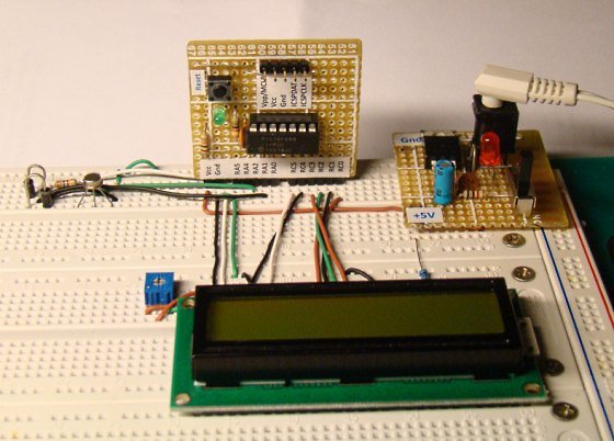
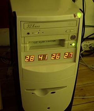
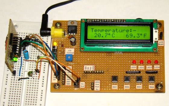
Single Chip Temperature Data Logger Description

The beauty of this project is that it uses just a single chip for logging. It is PIC12F683, an 8?pin microcontroller from Microchip. PIC12F683 has six general purpose I/O (GP0?GP5, GP3 is input only) pins, and 2K x 14 Flash program memory
with 256 bytes of internal EEPROM.

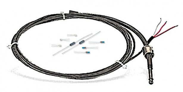
Temperature will be measured with a DS1820 temperature sensor. DS1820 is a one wire digital temperature sensor from Dallas Semiconductor (now MAXIM). The operating temperature range of the device is -55°C to +125°C with an accuracy of ±0.5°C over the range of -10°C to +85°C. The temperature sensor output is 9?bit Celsius temperature measurement, and so the temperature resolution corresponds to the least significant bit, and which is 0.5°C. But in this project we will use only the most significant eight bits. Therefore, the temperature resolution will be 1°C. The measured temperatures will be recorded into the internal EEPROM memory of PIC12F683.

The first location of the internal EEPROM will store the sampling interval of data logger. Sampling interval defines the time gap between two successive measurements. This project will have 3 options for sampling time: 1 sec, 1 min, and 10 min. These are user selectable. The second location of EEPROM will store the number of measurements recorded so far. And the remaining 254 EEPROM locations will store 8?bit temperatures. So, using 10 min sampling interval, 254 bytes of EEPROM will provide data logging for 42 hours. The recorded measurements can be sent to PC at any time through a serial link at 9600 baud.
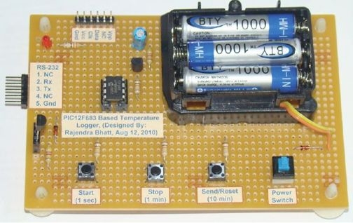
User Inputs

There will be three tact switches for user inputs, namely Start, Stop, and Send/Reset. The three switches will be able to accept the following 4 user requests.

1. Start: When ‘Start’ button is pressed, data logging starts.
2. Stop: Once the ‘Stop’ button is pressed, data recording will stop.
3. Send: Transfer data to PC through serial port.
4. Reset: Holding the ‘Send’ button for 2 sec or more clears the internal EEPROM memory.
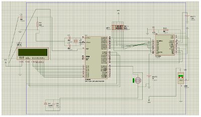
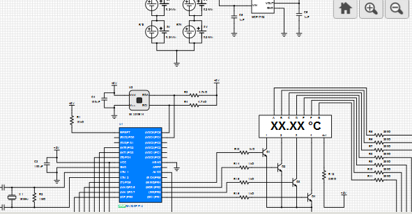
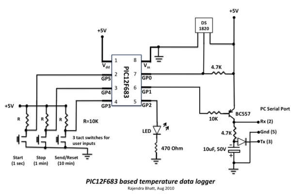
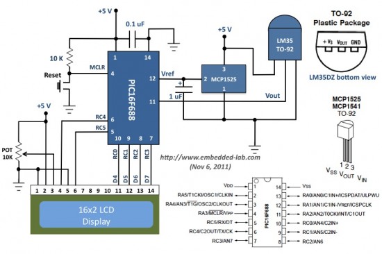
Single Chip Temperature Data Logger SchematicSampling Time Selection


The sampling interval can be selected as 1 sec, 1min, or 10 min using the same three switches. Suppose if we need 1 min sampling time, first turn OFF the power, then hold the ‘Stop’ button, turn the power ON, and wait till the LED glows. Once the LED glows, release the button, and the sampling interval will be set to 1 min. The new set sampling time will be updated to EEPROM location 0 so that in case of power failure, the previous sampling time will be restored. Similarly, use ‘Start’ and ‘Send’ buttons for 1 sec, and 10 min sampling intervals respectively.

LED Indicator

Every time the user presses input buttons, LED glows for a moment to indicate that the input is accepted. It also blinks thrice every time EEPROM Write operation takes place. It also blinks at the beginning when the power is turned ‘ON’. It also glows when the EEPROM memory is full.

For more detail: Single Chip Temperature Data Logger 

Current Project / Post can also be found using:

  • how to use pic16f877a to build thermometer

The post Single Chip Temperature Data Logger appeared first on PIC Microcontroller.

Temperature Controlled Fan

$
0
0

I’m currently mainly working on my new anemometer design but once in a while I get distracted. For example when my Keysight E3645A lab power supply was making so much noise that I could hardly concentrate. That’s when the idea of this fan controller was born.Of course, the best temperature controlled fan in the world doesn’t help if you really need the cooling the fan is providing. But very often a small fraction of the cooling would do just fine most of the time. In my case the supply does control the speed of the fan. But it doesn’t seem to measure the temperature at all but seems to calculate the necessary cooling in a worst-case condition.

Temperature Controlled Fan

An for a supply that may be rack-mounted together with lots of other heat dissipating gear the worst-case might be quite demanding. But my supply just sits on a shelf at, say, 22 degrees ambiant. And most of the time I’m hardly pulling any current. When working with microcontroller designs it’s rare for me to pull more than a few tens of milliamps. So little cooling is needed most of the time. But the E3645A (this one here does a better job) ran its fan at crazy speeds while the case still had this cold metallic feel to it.  So we can definitely do better.So the first step was to open the supply and to see what kind of fan it uses and how it is controlled. After beaking some seals and opening the case I found a 60x60x25mm 12V fan of Chinese origin. I also found out that the supply uses linear control. So there’s no PWM or anything but the supply voltage just varies in (I think) four steps from 7.4 to 12 volts. Most surprisingly, this voltage is not ground-referenced but symmetric around ground, i.e. plus/minus 6 volts.I was pleased to see that the fan connects to the main board by means of a standard two-pin 100mil header. So I could just plug anything in between the board and the fan.That’s exactly what my first idea was. Stick with the original fan and just put a PWM controller in between. I’ve just recently made some LED dimmers and the technology needed here seemed to be very similar. So Rev A of my fan controller was born.

For more detail: Temperature Controlled Fan

The post Temperature Controlled Fan appeared first on PIC Microcontroller.

PIC16F877A-Based Temperature Monitoring System

$
0
0

Temperature monitoring and control is important in industry environments. Sensors are widely used for measurement of temperature. Usually, a temperature sensor converts the temperature into an equivalent voltage output. IC LM35 is such a sensor. Here we describe a simple temperature measurement and display system based on LM35 sensor and PIC16F877A microcontroller. The temperature in degrees Celsius is displayed on a 16×2 LCD.PIC16F877A-Based Temperature Monitoring System

Fig.1 shows the functional block diagram of the PIC16F877A-based temperature monitoring system. The key features of this system are:

1. Continuous monitoring of temperature with 1-second update interval (which can be varied in the program).

2. Temperature measurement using LM35 precision integrated-circuit sensor.

3. Precise analogue-to-digital conversion using in-built 10-bit analogue- to-digital converter (ADC) of PIC16F877A microcontroller.

Hardware description

Fig.2.shows the circuit of the temperature monitoring system. The circuit mainly consists of the LM35 temperature sensor, PIC16F877A microcontroller and HD44780 controller based 16×2 LCD.

Schematic PIC16F877A-Based Temperature Monitoring System

Fig.2: Circuit of PIC16F877A-based temperature monitoring system

The output of the sensor is fed to the internal ADC of the microcontroller. Pin 2 of the microcontroller (RA0/AN0) is channel-1 of the internal ADC. The analogue voltage output of the sensor is converted into its equivalent digital value by the ADC and then its equivalent degree Celsius value is calculated by the software. The calculated temperature value is displayed on the LCD.

LM35 sensor. Fig.3 shows the pin configuration of LM35. It is a precision integrated-circuit centigrade temperature sensor whose output voltage is linearly proportional to the Celsius (Centigrade) temperature. The LM35 thus has an advantage over linear temperature sensors calibrated in degree Kelvin, as the user is not required to subtract a large constant voltage from its output to obtain convenient Centigrade scaling. For each degree Celsius change in temperature, the sensor output changes by 10 mV.

For more detail: PIC16F877A-Based Temperature Monitoring System

The post PIC16F877A-Based Temperature Monitoring System appeared first on PIC Microcontroller.


Revised version of LM35 based digital temperature meter

$
0
0

This is a revised version of my LM35 based digital thermometer project that I posted last year. Although it is one of the simplest projects, it is very popular among newbies who are just starting to learn microcontrollers. There was a little flaw in the original project as pointed by some readers. I was using a 1.2 V reference for A/D conversion with PIC16F688 microcontroller. However, the PIC16F688 datasheet says Vref should be equal to or higher than 2.2 V to ensure 1 LSB accuracy of A/D conversion. Here, I am rewriting the same project but this time I am using a MCP1525 IC to generate a precise 2.5 V reference for A/D conversion. This will improve the accuracy of temperature measurements.

Revised version of LM35 based digital temperature meter

Interfacing LM35 temperature sensor with a PIC microcontroller

Theory

The LM35 series of analog temperature sensors are produced by National Semiconductor Corporation and are rated to operate over a -55 °C to 150 °C temperature range. These sensors do not require any external calibration. The output voltage is proportional to the temperature, and the temperature-to-voltage conversion factor is 10 mV per °C. The sensor does not have any DC offset output voltage (which means the output is 0V at 0 °C temperature) and therefore, a negative voltage source is required in order to measure temperatures below 0 °C. For simplicity, the setup shown here is made to measure temperatures above 0 °C only. The PIC16F688 microcontroller reads the analog output voltage from the sensor through one of its ADC channel and derives the temperature information out of it.

For the maximum temperature value of 150 °C, the output voltage of the sensor would be 150 x 10 mV = 1. 5 V. If we use Vref = 5.0 V (power supply voltage) for A/D conversion, the resolution would be poor as the input signal goes only up to 1.5 V. Besides, if the supply voltage is not stable, it won’t be a good idea to use it as  Vref for A/D conversion. Using a lower and more stable Vref voltage can improve both the resolution and the accuracy of A/D measurements. However, the datasheet of PIC16F688 microcontroller recommends to use reference voltage above 2.2 V to ensure 1 LSB accuracy of A/D conversion. The MCP1525 IC from Microchip provides a precise output voltage of 2.5 V, which could serve this purpose. This device is also available in TO-92 package, and therefore, it can be wired on a breadboard too.

Circuit diagram

The revised circuit diagram of the project is shown below. All the connections remain the same, except the two diodes and a resistor in the original circuit are replaced by a MCP1525 device.

Schematic Revised version of LM35 based digital temperature meter

Revised circuit diagram (click the image to enlarge)

The whole setup of this project is shown below. For illustrative purpose, I am using the LCD display from my I/O board project here. Don’t get confused with all the LEDs and tact switches on the board, they should be disregarded. I am only using the LCD part of it.

For more detail: Revised version of LM35 based digital temperature meter

The post Revised version of LM35 based digital temperature meter appeared first on PIC Microcontroller.

Low cost temperature data logger using PIC and Processing

$
0
0

This project describes an easy and inexpensive way of adding a digital thermometer and data logging feature to a PC. It involves a PIC microcontroller that gets the surrounding temperature information from the Microchip MCP9701 sensor, and sends it to a PC through an USB-UART interface. The USB port of the PC is also used to power the device. The open-source Processing  programming platform is used to develop a PC application that displays the temperature in a graphics window on the computer screen. The PC application also records the temperature samples plus date and time stamps on an ASCII file.

Low cost temperature data logger using PIC and Processing

PC-based temperature data logger

Theory of operation

This project is based on Microchip’s PIC12F1822 microcontroller from the enhanced mid-range PIC family. It has got 8-pins in total and the power supply voltage range of 1.8V to 5.5V. The microcontroller has four 10-bit ADC channels and one Enhanced Universal Synchronous Asynchronous Receiver Transmitter (EUSART) module for serial communication. The temperature sensor used here is MCP9701A, which is a Low-Power Linear Active Thermistor IC from Microchip Technology. The range of temperature measurement is from -40°C to +125°C. The output voltage of the sensor is directly proportional to the measured temperature and is calibrated to a slope of 19.53mV/°C. It has a DC offset of 400mV, which corresponds to 0°C. The offset allows reading negative temperatures without the need for a negative supply. The output of the sensor is fed to one of the ADC channels of the PIC12F1822 microcontroller for A/D conversion. The internal fixed voltage reference (FVR) module is configured to generate a stable 2.048 V reference voltage for A/D conversion. The use of FVR module ensures the accuracy of the A/D conversion even when the supply voltage is not stable. The PIC12F1822 microcontroller then serially transmits the 10-bit ADC output to a PC.

Modern PCs are no more equipped with serial ports and therefore this project requires a USB-UART adapter that enables very easy connection of the PIC12F1822 to the PC via the USB port. You can get them really cheap on ebay. I bought one for $3.39 (see the picture below) from here: http://cgi.ebay.com/ws/eBayISAPI.dll?ViewItem&item=370532286388
It can be directly interfaced to the TTL input and output of EUSART module of PIC12F1822. This module also provides +5 V, +3.3 V, and ground terminals. The power supply for the microcontroller circuit is derived from the same +5 V and ground pins.

On PC’s side, the open source programming language Processing is used to receive the ADC output and convert it into the actual temperature. The temperature is displayed on a graphics window on the computer screen in numeric format as well as with a wall tube thermometer looking image where the level of alcohol rises with increasing temperature. A clickable Start/Stop button also appears on the window to enable or disable the data logging.

Circuit diagram

The circuit diagram of this project is pretty simple. The microcontroller reads the temperature sensor’s output through RA2/AN2 pin and convert it to a 10-bit digital number. The Tx (RA0) and Rx (RA1) port of the EUSART module are connected to the corresponding pins of the USB-UART module. The microcontroller runs at 4.0 MHz using an internal clock source. Although I have disabled the MCLR function here, you can use it for an external reset if you want.Schematic Low cost temperature data logger using PIC and ProcessingFor more detail: Low cost temperature data logger using PIC and Processing

The post Low cost temperature data logger using PIC and Processing appeared first on PIC Microcontroller.

A Beginner’s data logger project using PIC12F683 microcontroller

$
0
0

It is a very simple data logger project based on PIC12F683 microcontroller. The microcontroller reads temperature values from a temperature sensor on a regular interval basis and stores them into its internal EEPROM memory. The recorded temperatures can be later transferred to a PC through serial interface. I originally published this project on electronics-lab.com last summer. I thought this could be a very good learning project for beginners, and so I am posting it here for Embedded Lab’s readers too.

A Beginner’s data logger project using PIC12F683 microcontroller

Finished temperature logger powered from a 9V battery

Theory

The sensor used in this project is DS18B20. It is a digital temperature sensor manufactured by Dallas Semiconductor (now MAXIM) that can measure temperature ranging from -55°C to +125°C with an accuracy of ±0.5°C over the range of -10°C to +85°C. The sensor provides the measured temperature (°C) output in user-configurable 9, 10, 11, or 12-bit data corresponding to the desired resolution of 0.5, 0.25, 0.125, and 0.0625 °C. The sensor communicates with a host microcontroller over a 1-wire bus. Readers are suggested to refer the datasheet on Maxim’s website for details on this sensor. Please keep in mind that there are three versions of this sensors, namely DS1820, DS18S20, and DS18B20, and they have some architectural differences. All of them have the same pin configuration and therefore the circuit diagram would be same for all three types. However, some modification in the software may be required while the microcontroller reads the temperature data from them.

PIC12F683 has 256 bytes of internal EEPROM. Each temperature reading is stored as a byte, which means only the eight most significant bits of DS18B20 output is recorded. Therefore, the temperature resolution is decreased down to 1 °C. This temperature logger can store up to 254 temperature values (254 bytes) in its internal EEPROM. The remaining two EEPROM locations are used to store the sampling time and number of samples information. Three tact switches are used to provide user inputs for controlling the operation of the data logger.

Circuit Diagram

The PIC microcontroller uses its internal clock source operated at 4.0 MHz. The DS18B20 sensor is interfaced to GP0 pin (7) of the microcontroller. An LED connected to the GP2 pin serves as the only display in the circuit to indicate various actions of the data logger. For example, it blinks every time a sample is recorded into EEPROM. The circuit is powered with +5 V derived from a 9V battery using an LM78L05 regulator IC. The LM78L05 circuit is a very common circuit and therefore, it is not shown here.

Schematic A Beginner’s data logger project using PIC12F683 microcontroller

Circuit diagram of data logger

The three tact switches provide the following functions.

  • Start: Starts data logging
  • Stop: Stops the logging procedure
  • Send/Reset: Transfers data to PC through serial port. However, if it is held pressed for 2 sec or more, the EEPROM locations are cleared and ready for new recordings.

Selection of sampling time

This data logger offers three options for sampling interval: 1 sec, 1min, and 10 min. The selection is made through the same three tact switches. Here is how it works. Suppose if 10 min sampling time is needed, then first turn OFF the power, hold the ‘Send/Reset’ button pressed, turn the power ON, and wait till the LED glows. Once the LED glows, release the button, and the sampling interval is set to 10 min. The new sampling time will be updated to EEPROM location 0 so that in case of power failure, the previous sampling time will be restored. Similarly, the use of ‘Start’ or ‘Stop’ button instead of the Send/Reset one sets the sampling time to  1 sec, or 1 min respectively. With 10 min sampling interval, this data logger can record temperature samples over 42 hours.

For more detail: A Beginner’s data logger project using PIC12F683 microcontroller

Current Project / Post can also be found using:

  • temperature measurement using ntc in 8051 microcontroller

The post A Beginner’s data logger project using PIC12F683 microcontroller appeared first on PIC Microcontroller.

A Digital temperature meter using an LM35 temperature sensor

$
0
0

Introduction

A digital thermometer is a good choice of project for beginners who just stepped in to the world of microcontrollers because it provides an opportunity to learn using sensors to measure the real world signals that are analog in nature. This article describes a similar project based on a PIC16F688 microcontroller and an LM35 temperature sensor. LM35 is an analog sensor that converts the surrounding temperature to a proportional analog voltage. The output from the sensor is connected to one of the ADC channel inputs of the PIC16F688 microcontroller to derive the equivalent temperature value in digital format. The computed temperature is displayed in a 16×2 character LCD, in both °C and °F scales.A Digital temperature meter using an LM35 temperature sensor

Theory

The LM35 series of temperature sensors are produced by National Semiconductor Corporation and are rated to operate over a -55 °C to 150°C temperature range. These sensors do not require any external calibration and the  output voltage is proportional to the temperature. The scale factor for temperature to voltage conversion is 10 mV per °C. The LM35 series sensors come in different packages. The one I used is in a hermatic TO-46 transistor package where the metal case is connected to the negative pin (Gnd).

The measurement of negative temperatures (below 0°C) requires a negative voltage source. However, this project does not use any negative voltage source, and therefore will demonstrate the use of sensor for measuring temperatures above 0°C (up to 100°C).

The output voltage from the sensor is converted to a 10-bit digital number using the internal ADC of the PIC16F688. Since the voltage to be measured by the ADC ranges from 0 to 1.0V (that corresponds to maximum temperature range, 100 °C), the ADC requires a lower reference voltage (instead of the supply voltage Vdd = 5V) for A/D conversion in order to get better accuracy. The lower reference voltage can be provided using a Zener diode,  a resistor network, or sometime just simple diodes. You can derive an approximate 1.2V reference voltage by connecting two diodes and a resistor in series across the supply voltage, as shown below. As a demonstration, I am going to use this circuit in this project. I measured the output voltage across the two diodes as 1.196 V. The resistor R I used is of 3.6K, but you can use 1K too. The important thing is to measure the voltage across the two diodes as accurate as possible.Schematic A Digital temperature meter using an LM35 temperature sensor

We need do some math for A/D conversion. Our Vref is 1.196 V, and the ADC is 10-bit. So, any input voltage from 0-1.196 will be mapped to a digital number between 0-1023. The resolution of ADC is 1.196/1024 = 0.001168 V/Count. Therefore, the digital output corresponding to any input voltage Vin = Vin/0.001168. Now, lets see how to get the temperature back from this whole process of converting sensor’s output to 10-bit digital number.

For more detail: A Digital temperature meter using an LM35 temperature sensor

The post A Digital temperature meter using an LM35 temperature sensor appeared first on PIC Microcontroller.

PIC based wireless temperature and heartbeat read-out

$
0
0

Microcontroller based wireless temperature and heartbeat read out suitable for a operation in a small office/home environment . This system is suitable to operate with Visual LCD. Many individuals or organisations may, for various reasons,wish to use electronic surveillance technique at some time or another. This idea is to use off the shelf RF Tx/Rx modules. The weather keeps us continually occupied. Some people have even made it their profession. At home too,we like to measure all kinds of things related to our climate.That is why weather stations are available in all types and sizes.

PIC based wireless temperature and heartbeat read-out If we want to know the temperature inside and outside then purpose built indoor/outdoor thermometers are available. In the past the outside sensor of these weather stations was connected with a wire, it is now fairly standard to use RF transmission for this data. The wireless transmitters units usually make use of the 315-MHz band. These modules, once a  rare commodity, are now widely and cheaply available. In this particular discussion, we shall be using ASK(Amplitude Shift Keying) based TX/RX pair operating at 315 MHz. The transmitter module accepts serial data at a maximum of 2400bps. They are directly interfaced to a microcontroller. At the RX end, the receiver microcontroller receives the signal via the RF receiver module,decodes the serial data and reproduces the original data in the temperature and Heart Beat format.

Temperature Sensor
 Temperature is one of the fundamental physical variables in most chemical and process control applications. Accurate and reliable measurements of the temperature is important in nearby all process control applications. Temperature sensors can be analog or digital. Some of the most commonly used analog temperature sensors are : thermocouples, resistance temperature detector ( RTD)s and thermistors. Digital sensors are in the form of integrated circuits.
PIC based wireless temperature and heartbeat read-out SchematicThe choice of a sensor depends on the accuracy, the temperature range, speed of response, thermal coupling, the environment (chemical, electrical, physical) and the cost. A popular voltage output analog integrated circuit temperature sensor is LM35DZ,manufactured by National Semiconductor. This is the 3 pin analog output sensor which provides a linear output voltage of 10 mV/degree Celsius. The temperature range is 0 to 100 degree Celsius, with an accuracy of +-1.5 degree Celsius.

The post PIC based wireless temperature and heartbeat read-out appeared first on PIC Microcontroller.

Viewing all 365 articles
Browse latest View live


<script src="https://jsc.adskeeper.com/r/s/rssing.com.1596347.js" async> </script>