Quantcast
Channel: temperature | Battery Guide
Viewing all 365 articles
Browse latest View live

Arduino powered temperature sensing RGB LED nightlight using PICaxe

$
0
0

About a year ago I started on a project to make a temperature controlled nightlight. I was inspired by seeing these lovely LED lamps styled as mushrooms growing out of pieces of wood. Those mushrooms were made out of glass, which was somewhat beyond my skills. However I then saw some had used translucent sculpey to make mushroom nightlights on instructables. So with that discovery it seemed like it would be rather simple to do…

temperature sensing RGB LED nightlight

The first job was to solder up a three colour (RGB) LED (a super bright one from oomlout):

I then covered the LED in translucent Fimo:

As Fimo only needs to be heated to about 100C to set it’s ok to do this, as it won’t hurt the LED. Also LEDs don’t normally give out much heat, so covering them is ok. Of course this is a relatively low power (though quite bright) LED as well which helps.

I found a branch on the way home from work, which I cut up and sanded down. This formed the base for the mushroom:

As you can see I also opted for a chunky on/off button, in the style of the original mushroom lamps.

Next I put a small electronics project box into the bottom of the piece of wood and made space for a slide switch and power socket

At the time I decided to try to use a Picaxe 08m chip to control the LED and read from a temperature sensor. The Picaxe 08m has a native function to read the temperature from a DS18B20 One Wire digital temperature sensor. It also had just about enough inputs and outputs to handle controller the three colors of the LED and reading from a slide switch (to make it switch between temperature display and plain nightlight). The individual chips were also pretty cheap, so it seemed like a good plan at the time.

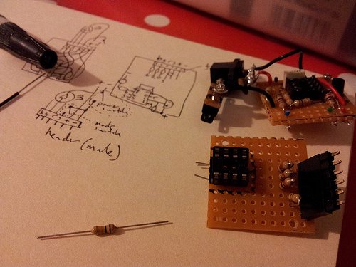
However the size of the circuit and number of components I needed to solder was all a bit too much for me:

temperature sensing RGB LED nightlight circuit

Eventually after much debugging I was able to get some things working – e.g. controlling the colour of the LED, but the temperature sensor just wouldn’t cooperate and always gave a high reading. I also managed to get through a few sensors due to mis-wiring them!

So I decided it was time to start again with the circuit. I bought a better soldering iron (a not too expensive digital temperature controlled one) and started on a new circuit:


For more detail: Arduino powered temperature sensing RGB LED nightlight using PICaxe

The post Arduino powered temperature sensing RGB LED nightlight using PICaxe appeared first on PIC Microcontroller.


Temperature compensation delivers from MEMS oscillator

$
0
0

The SiT5003 is the most flexible LVCMOS/LVTTL/HCMOS compatible, ultra-stable MEMS VCTCXO (Voltage Controlled, Temperature Compensated Oscillator) solution in the market. This device supports any combination of the following features: frequency (1 – 80MHz), voltage (1.8V, 2.5V-3.3V), stability (±0.5PPM), pull range (±12.5PPM to ±50PPM) and 4-pin packages (3225, 5032, 7050). It provides superior shock and vibration resistance, and 2 FIT reliability that is 10 times better than crystal VCTCXO and TCXO oscillators and is ideal for high reliability applications in telecom, networking, wireless and embedded. SiTime’s MEMS devices are 100% compatible with legacy quartz crystal VCTCXO and TCXO oscillators in footprint and package, and replace these devices without any design changes.

Features

  • Excellent frequency stability of ±0.5 PPM over industrial temperature range (-40 to +85°C)
  •     Excellent timing margin for high reliablity systems like GPS
  •     Extensive programmability
  •   Any frequency from 1MHz to 80MHz with 6 decimal places of accuracy and without any coverage gaps that are always present in crystal VCTCXO and TCXO oscillators
  •         Supply voltage of 1.8V, 2.5V to 3.3V (continuous)
  •         Voltage control option, pull range from ±12.5 PPM to ±50 PPM
  •         Configurable drive strength
  • Customized specification for optimal system performance
  •     Easy availability of any device specification within the operating range
    Improve system robustenss in all operating environments
    Reduce field failures due to clock components and the repair cost

Temperature compensation delivers from MEMS oscillator

A US team has created a silicon frequency reference with frequency stability better than +/-0.5ppm from -40 to 85°C, along with Allan deviation (long term jitter) better than 0.005ppm for 0.1, 1, and 10s strides.

It is a two chip solution: a MEMS chip on top of CMOS circuitry, with a thermistor on the MEMS used to cut errors “since the MEMS resonator has a well-defined temperature dependence”, said the researchers.

From a raw temperature coefficient around -31ppm/K, 5th-order polynomial correction is applied digitally to get the final stability.

The design uses a complex chopper-based temperature to digital converter that suppresses electromigration-induced drift by keeping DC current through the thermistor close to zero.

Set to 48MHz output with no load, current consumption is 33mA from 3.3V.

Measured current consumption for all analogue and digital circuits in the temperature to digital converter and clock multiplier is 3.93mA.

The development team were at SiTime in Sunnyvale, and the temperature to digital converter was reported in detail at ISSCC 2012 in San Francisco.

“The work has resulted in a product for SiTime, the SiT5003“, Piyush Sevalia, v-p of marketing at the firm, told Electronics Weekly.


For more read: temperature compensation delivers from MEMS oscillator

The post Temperature compensation delivers from MEMS oscillator appeared first on PIC Microcontroller.

Maxim adds mosfets to ‘smallest’ DC-DC converter

$
0
0

Description

Create a design and simulate using EE-Sim: [MAX15058]

The MAX15058 high-efficiency, current-mode, synchronous step-down switching regulator with integrated power switches delivers up to 3A of output current. The device operates from 2.7V to 5.5V and provides an output voltage from 0.6V up to 94% of the input voltage, making the device ideal for distributed power systems, portable devices, and preregulation applications.

The MAX15058 utilizes a current-mode control architecture with a high-gain transconductance error amplifier. The current-mode control architecture facilitates easy compensation design and ensures cycle-by-cycle current limit with fast response to line and load transients.

The MAX15058 offers selectable skip-mode functionality to reduce current consumption and achieve a higher efficiency at light output load. The low RDS(ON) integrated switches ensure high efficiency at heavy loads while minimizing critical inductances, making the layout design a much simpler task with respect to discrete solutions. Utilizing a simple layout and footprint assures first-pass success in new designs.

The MAX15058 features a 1MHz, factory-trimmed, fixed-frequency PWM mode operation. The high switching frequency, along with the PWM current-mode architecture, allows for a compact, all-ceramic capacitor design.

Maxim adds mosfets to ‘smallest’ DC-DC converter

Key Features

  • Internal 30mΩ (typ) RDS(ON) High-Side and 18mΩ (typ) Low-Side MOSFETs at 5V
  • Continuous 3A Output Current Over Temperature
  • 95% Efficiency with 3.3V Output at 3A
  • 1% Output Voltage Accuracy Over Load, Line, and Temperature
  • Operates from 2.7V to 5.5V Supply
  • Cycle-by-Cycle Overcurrent Protection
  • Adjustable Output from 0.6V to Up to 0.94 x VIN
  • Programmable Soft-Start
  • Factory-Trimmed, 1MHz Switching Frequency
  • Stable with Low-ESR Ceramic Output Capacitors
  • Safe-Startup Into Prebiased Output
  • External Reference Input
  • Skip-Mode Functionality
  • Enable Input/Power-Good Output
  • Fully Protected Against Overcurrent and Overtemperature
  • Input Undervoltage Lockout

Maxim claims to have designed the smallest current-mode, synchronous DC-DC converter capable of delivering up to 18A of output current.

The DC-DC regulator integrates the mosfets in a wafer-level package measuring just 2mm x 3.5mm.

The converter can operate in fixed pulse-width modulation (PWM) mode or configured for pulse-skip mode, which means it can cut power during light load conditions.

There are four converters in the range – MAX15058/MAX15108/MAX15112/MAX15118 operate from a 2.7V to 5.5V input voltage with output current of 3, 8, 12, and 18A, respectively. They are designed to provide ±1% output-voltage accuracy over load, line, and temperature.


For more read: Maxim adds mosfets to ‘smallest’ DC-DC converter

The post Maxim adds mosfets to ‘smallest’ DC-DC converter appeared first on PIC Microcontroller.

Humidity and temperature measurements with Sensirion’s SHT1x/SHT7x sensors (Part 1) using pic microcontoller

$
0
0
Temperature and relative humidity are two very important ambient parameters that are directly related to human comfort. Sometimes, you may be able to bear higher temperatures, if there is a lower relative humidity, such as in hot and dry desert-like environment. However, being in a humid place with not very high temperature may make you feel like melting. This is because if there is high relative humidity, sweat from our body will evaporate less into the air and we feel much hotter than the actual temperature. Humidifiers and dehumidifiers help to keep indoor humidity at a comfortable level. Today we will discuss about Sensirion’s SHT series of digital sensors, more specifically SHT11 and SHT75, which are capable of measuring both temperature and relative humidity and provide fully calibrated digital outputs. We will interface both the sensors to PIC18F2550 microcontroller and compare the two sets of  measurements to see the consistency between the two sensors. This tutorial is divided into two parts. The first part will cover all the details regarding the sensors, including their specification, interface, and communication protocol. The second part will be more focussed on the circuit diagram, implementation of the communication protocol with PICMicro, and the results.
Humidity and temperature measurements with Sensirion’s SHT1x SHT7x sensors (Part 1)Theory

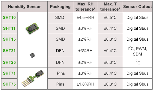
Sensirion offers multiple SHT series of digital sensors for measuring both relative humidity and temperature. The temperature is measured using a band-gap sensor, whereas the humidity sensor is capacitive; which means the presence of moisture in air changes the dielectric constant of the material in between the two plates of a parallel-plate capacitor, and hence varies the capacitance. The required signal conditioning, analog-to-digital conversion, and digital interface circuitries are all integrated onto the sensor chip. The various SHT series sensors have different levels of accuracy for humidity and temperature measurements, as described below.

SHT1x are available in surface mount type whereas SHT7x are supplied with four pins which allows easy connection. The SHT11 and SHT75 sensors both provide fully calibrated digital outputs that can be read through a two-wire (SDA for data and SCK for clock) serial interface which looks like I2C but actually it is not compatible with I2C. An external pull-up resistor is required to pull the signal high on the SDA line. However, the SCK line could be driven without any pull-up resistor. The signaling detail of the serial bus is described in the datasheet, which we will implement for PIC18F2550 microcontroller using mikroC pro for PIC compiler. The operating range of both the sensors is 0 to 100% for relative humidity, and -40.0 to 123.8 °C for temperature. The sensor consumes 3 mW power during measurement, and 5 ?W, while in sleep mode.

The SHT11 module that I have got is from mikroElektronika. The sensor (SMD) is soldered on a tiny proto board with all the four pins accessible through a standard 0.1 inch spacing male header. The board comes with pull-up resistors connected to both SDA and SCK lines. One concern in this type of arrangement is the heat dissipated by the pull-up resistors could affect the measurements if the resistors and the sensor are close in the board. We will discuss about this issue later too. The SHT75 module from Sensirion, however, does not include any pull-up resistor for SDA line and therefore must be included externally.

Brief description of SHT1x/7x sensors

Please read the datasheets for SHT1x and SHT7x for detail information about these sensors. I am only providing a brief summary here.

SHT11 and SHT75 are functionally same with SHT75 being more accurate (±1.8% vs ±3%) in measuring relative humidity. Both the sensors can operate from 2.4-5.5 V supply voltage, however the datasheet recommends to use 3.3V for highest accuracy. The default measurement resolution is 14-bit for temperature and 12-bit for relative humidity, which can be reduced to 12- and 8-bit respectively by changing the bit settings of the Status Register (discussed later) inside the sensor chip. We will be using the default resolution settings for measurements.

Humidity and temperature measurements with Sensirion’s SHT1x SHT7x sensors (Part 1)SCK is the clock line that is used to synchronize the communication between the micrcontroller and the sensor. It is an input only pin on the sensor’s side and therefore the microcontroller should be responsible to generate the clock signal. DATA or SDA is a bidirectional data transfer pin for sending data in and out of the sensor. The sensor should receive a conversion command from the microcontroller in order to start measuring temperature or relative humidity. The measurement commands for relative humidity and temperature are 00000101 (05H) and 0000011 (03H), respectively [The first three most-significant bits are actually the address bits, which are always zero for SHT1x and SHT7x sensors, and the remaining 5 bits are the command bits]. Prior to sending a command, a Transmission Start sequence must be issued by the microcontroller which consists of a lowering of the DATA line while SCK is high, followed by a low pulse on SCK and raising the DATA line high again, while the SCK is already high.


The post Humidity and temperature measurements with Sensirion’s SHT1x/SHT7x sensors (Part 1) using pic microcontoller appeared first on PIC Microcontroller.

Interfacing DHT11 humidity and temperature sensor with PIC16F877A using pic microcontoller

$
0
0

After interfacing the DHT11 with Arduino uno board at the following post:
ARDUINO Humidity & Temperature Measurement Using DHT11 Sensor
Now we are going to see how to interface this sensor with microchip pic16f877a.
There are some descriptions of how this sensor work  in the above link

A brief description of the code:
The code is written using MikroC compiler.
 First we must send a start signal to the sensor, we do that by configuring the pic pin connected to the sensor as output, the mcu sends 0 for 18ms then sends 1 for 30us.
After sending start signal to the sensor, the sensor will send a response signal to the mcu. To detect this signal mcu pin must be configured as input.
When the sensor finishes the response signal, it begins sending humidity and temperature data serially.
If there is a problem with the sensor or there is no sensor connected to the circuit, the LCD displays “there is no response from the sensor”. And if there is a problem in the sensor which means the values are incorrect the LCD displays “Check sum error”.
Interfacing DHT11 humidity and temperature sensor with PIC16F877A
// LCD module connections
 sbit LCD_RS at RB5_bit;
 sbit LCD_EN at RB4_bit;
 sbit LCD_D4 at RB3_bit;
 sbit LCD_D5 at RB2_bit;
 sbit LCD_D6 at RB1_bit;
 sbit LCD_D7 at RB0_bit;
 sbit LCD_RS_Direction at TRISB5_bit;
 sbit LCD_EN_Direction at TRISB4_bit;
 sbit LCD_D4_Direction at TRISB3_bit;
 sbit LCD_D5_Direction at TRISB2_bit;
 sbit LCD_D6_Direction at TRISB1_bit; 
 sbit LCD_D7_Direction at TRISB0_bit;
 // End LCD module connections
 char *text,mytext[4];
 unsigned char  a = 0, b = 0,i = 0,t1 = 0,t2 = 0,
               rh1 = 0,rh2 = 0,sum = 0;
 void StartSignal(){
 TRISD.F2 = 0;    //Configure RD2 as output
 PORTD.F2 = 0;    //RD2 sends 0 to the sensor
 delay_ms(18);
 PORTD.F2 = 1;    //RD2 sends 1 to the sensor
 delay_us(30);
 TRISD.F2 = 1;    //Configure RD2 as input
  }
 void CheckResponse(){
 a = 0;
 delay_us(40);
 if (PORTD.F2 == 0){
 delay_us(80);
 if (PORTD.F2 == 1)   a = 1;   delay_us(40);}
 }
 void ReadData(){
 for(b=0;b<8;b++){
 while(!PORTD.F2); //Wait until PORTD.F2 goes HIGH
 delay_us(30);
 if(PORTD.F2 == 0)    i&=~(1<<(7-b));  //Clear bit (7-b)
 else{i|= (1<<(7-b));               //Set bit (7-b)
 while(PORTD.F2);}  //Wait until PORTD.F2 goes LOW
 }
 }
 void main() {
 TRISB = 0;        //Configure PORTB as output
 PORTB = 0;        //Initial value of PORTB
 Lcd_Init();
 while(1){
 Lcd_Cmd(_LCD_CURSOR_OFF);        // cursor off
 Lcd_Cmd(_LCD_CLEAR);             // clear LCD
  StartSignal();
  CheckResponse();
  if(a == 1){
  ReadData();
  rh1 =i;
  ReadData();
  rh2 =i;
  ReadData();
  t1 =i;
  ReadData();
  t2 =i;
  ReadData();
  sum = i;
  if(sum == rh1+rh2+t1+t2){
  text = "Temp:  .0C";
  Lcd_Out(1,6,text);
  text = "Humidity:  .0%";
  Lcd_Out(2,2,text);
  ByteToStr(t1,mytext);
  Lcd_Out(1,11,Ltrim(mytext));
  ByteToStr(rh1,mytext);
  Lcd_Out(2,11,Ltrim(mytext));}
  else{
  Lcd_Cmd(_LCD_CURSOR_OFF);        // cursor off
  Lcd_Cmd(_LCD_CLEAR);             // clear LCD
  text = "Check sum error";
  Lcd_Out(1,1,text);}
  }
  else { 
  text="No response";
  Lcd_Out(1,3,text);
  text = "from the sensor";
  Lcd_Out(2,1,text);
  }
  delay_ms(2000);
  }
  }

Saturday, November 8, 2014

PIC16F877A LCD Example

This is just an example to show how to interface 16×2 lcd with pic16f877a. The lcd is going to display “PIC16F877A” in the the first line and “LCD Example” in the second line. The code is written using MikroC compiler.
// LCD module connections
sbit LCD_RS at RB5_bit;
sbit LCD_EN at RB4_bit;
sbit LCD_D4 at RB3_bit;
sbit LCD_D5 at RB2_bit;
sbit LCD_D6 at RB1_bit;
sbit LCD_D7 at RB0_bit;
sbit LCD_RS_Direction at TRISB5_bit;
sbit LCD_EN_Direction at TRISB4_bit;
sbit LCD_D4_Direction at TRISB3_bit;
sbit LCD_D5_Direction at TRISB2_bit;
sbit LCD_D6_Direction at TRISB1_bit;
sbit LCD_D7_Direction at TRISB0_bit;
// End LCD module connections
char *text;
void main() {
TRISB = 0;
PORTB = 0;
Lcd_Init();
Lcd_Cmd(_LCD_CURSOR_OFF);        // cursor off
Lcd_Cmd(_LCD_CLEAR);             // clear LCD
text = "PIC16F877A" ;
Lcd_Out(1,4,text);
text = "LCD Example";
Lcd_Out(2,4,text);
while(1);                     //infinite loop
}

Interfacing DHT11 humidity and temperature sensor with PIC16F877ATuesday, November 4, 2014

Real Time Clock

Now, I’m going to work with real time clocks, for that I will use the integrated circuit DS1307serial real time clock. I will use this ic with Arduino uno board and also I have to return to the pic microcontroller chip PIC16F877A. For the pic mcu I will use Microc and the full codes and schematics will be available on the next posts.
The DS1307 provides clock and calender. The clock shows seconds, minutes and hours and the calender shows day, month and year. The ds1307 uses I2C serial interface to transfer information with the microcontroller. More information in its datasheet.

Cd-Rom 3 phase Sensored BLDC Motor Arduino Controller

BLDC (brushless dc) motors are three phase dc motors, unlike the simple dc motors the bldc motors are more difficult to control. These motors are used in many applications for examples rc airplans and rc cars.
In this post we will see how to control cd-rom sensored BLDC motor using Arduino uno board. But first there are some things we should know in order to control the motor in easy way.
The bldc motor that we are going to use is sensored via hall effect sensors (position sensors) attached with the motor(3 sensors). Each sensor outputs digital high for 180 electrical degrees and low for the other 180 electrical degrees.these sensors are used to tell us where is the position of the motor, then when we know the position of the motor we will energize just tow windings (of three). The below figure shows how sensors outputs and the corresponding voltage applied to the motor:

The post Interfacing DHT11 humidity and temperature sensor with PIC16F877A using pic microcontoller appeared first on PIC Microcontroller.

Digital Thermometer using PIC Microcontroller and LM35 Temperature Sensor

$
0
0

A Digital Thermometer can be easily constructed using a PIC Microcontroller and LM35 Temperature Sensor. LM35 series is a low cost and precision Integrated Circuit Temperature Sensor whose output voltage is proportional to Centigrade temperature scale. Thus LM35 has an advantage over other temperature sensors calibrated in Kelvin as the users don’t require subtraction of large constant voltage to obtain the required Centigrade temperature.

Digital Thermometer using PIC Microcontroller and LM35 Temperature SensorIt doesn’t requires any external calibration. It is produced by National Semiconductor and can operate over a -55 °C to 150 °C temperature range. Its output is linearly proportional to Centigrade Temperature Scale and it output changes by 10 mV per °C.

The LM35 Temperature Sensor has Zero offset voltage, which means that the Output = 0V,  at 0 °C. Thus for the maximum temperature value (150 °C), the maximum output voltage of the sensor would be 150 * 10 mV = 1.5V.  If we use the supply voltage (5V) as the Vref+ for Analog to Digital Conversion (ADC) the resolution will be poor as the input voltage will goes only up to 1.5V and the power supply voltage variations may affects ADC output. So it is better to use a stable low voltage above 1.5 as Vref+. We should supply Negative voltage instead of GND to LM35 for measuring negative Temperatures.

Digital Thermometer using PIC Microcontroller and LM35 Temperature SensorThis article only covers the basic working of Digital Thermometer using PIC Microcontroller and LM35, and uses 5V as Vref+. If you want more accurate results it is better to select Vref+ above 2.2V. I suggest you to use  MCP1525 IC manufactured by Microchip, which will provide precise output voltage 2.5.


For more detail: Digital Thermometer using PIC Microcontroller and LM35 Temperature Sensor

The post Digital Thermometer using PIC Microcontroller and LM35 Temperature Sensor appeared first on PIC Microcontroller.

High-temperature versions of MEC switches now for the price of standard versions.

$
0
0

ompany MEC, Dutch producer of top-class push-button switches Multimec, Unimec and others comes with good news for developers and producers of electronics.

Well-known reliable push-buttons were in majority of cases available in so called standard version (L6, -40…+115°C) and in a high-temperature version (H9, -40…+160°C).

High-temperature versions of MEC switches now for the price of standard versions. From now on, all types will be gradually available only in a „high temperature“ version, which can be identified by „H9“marking in suffix. This applies to Multimec 3 and Unimec series (series Multimec 5 is already from the beginning only available in a high-temperature version).

The main „good news“ is, that these high-temperature types will be available for practically identical prices like standard types. That´s why, even in applications where you wouldn´t necessarily need that high thermal resistance, you can use this high-temp version and profit from unchanged price and potentially wider possibilities of usage of your product.

The most suitable type for you application can be easily found in the MEC catalogue (11MB).


For more detail: High-temperature versions of MEC switches now for the price of standard versions. 

The post High-temperature versions of MEC switches now for the price of standard versions. appeared first on PIC Microcontroller.

12F675 Tutorial 5 : A Temperature data logger using PIC EEPROM. using pic microcontroller

$
0
0

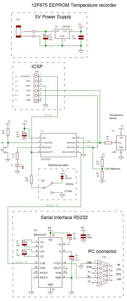
EEPROM is useful for storing long term data such as data logger information and this PIC microcontroller EEPROM project saves the temperature from an LM35DZ IC to the PIC’s internal long term data storage area.  The project follows on from the last project using the virtually the same hardware.
It stores temperature readings internally at regular intervals until full and after this it turns on the LED. The LED is really just for showing that something is happening and in a real data logger you would not use it.
12F675 Tutorial 5 A Temperature  data logger using PIC EEPROM.Jump to Solderless breadboard.
Jump to Circuit Diagram.
Jump to Software.

Note: This project is not optimized for power consumption so the best way to use it is powered from a power block.  The current consumed is about 13mA (LED off) 16mA (LED on at end). If you want to use a battery use a rechargeable PP3 and do not attach the LED.

The 12F675 may not the best PIC microcontroller to use for low power data logging and a better choice would be the 16F88 as it can change its internal oscillator on the fly going into slow (current saving) mode.  But you could use the 12F675 with a slow external 32kHz crystal. 

At every ADC reading the LED is flashed briefly and when you select a 500ms reading interval you can see the readings being taken.  When 64 readings are accumulated the LED is lit permanently – showing that the data store is full.


Note: For this chip you only get to store 64 results as you need to store an unsigned integer for every ADC result and this takes 2 bytes so 128 Bytes/2  = 64 results.
You can hit the button at any time and the contents of the EEPROM will be read from the internal EEPROM and transmitted to the PC via the serial port.

To erase the internal EEPROM hold the button and cycle the power – this flashes the led 6 times indicating erase (normal startup flashes the LED 3 times).

Solderless breadboard

The solderless breadboard and circuit diagram are nearly the same as used in the previous project so if you have already built it you don’t need to do any more.  Just add the blue wire, D2 and R6.

12F675 Tutorial 5 A Temperature  data logger using PIC EEPROM.

Circuit diagram

Note that the switch shown below is just a blue wire above. Either leave the  blue wire where it is to hold the input, at pin 4, high or move the top of the blue wire to ground (0V – green wires at top left – on the left of the solderless breadboard) to set GP3 (pin 4) low.

Note: The diode stops the programming voltage conflicting with the 5V power supply – reversed biased when the high programming voltage is present.


For more detail: 12F675 Tutorial 5 : A Temperature  data logger using PIC EEPROM.

The post 12F675 Tutorial 5 : A Temperature data logger using PIC EEPROM. using pic microcontroller appeared first on PIC Microcontroller.


Even the humidity & temperature sensors can be „3G“

$
0
0

Even the actual series like SHT1x and SHT2x belong to a top in this segment. Forthcoming series SHT3x (SHT30, SHT31 and soon also SHT35) addresses mainly those of you, requiring maximum accuracy even in limit values (humidity below 10% and above 90%), miniature dimensions and ultra low power consumption. So a main difference of a new SHT31 compared to SHT21 is, that a typical +-2% is maintained in a whole range.

Even the humidity & temperature sensors can be „3G“Together with a precise temperature measurement in element we still have a possibility to simply compute a dew point, what´s one of the key parameters for ventilation control (HVAC, heat recovery). If it´s “only” necessary to guide a humidity not to exceed certain level, then you´ll probably also use the output „Alert“ pin, able to start interrupt in a host MCU for instance or directly control further devices. Output of the SHT3x sensor is the linearized value, which can be easily transformed to a final value (%RH, °C).

SHT31 is available in 2 versions – SHT31-DIS-B with a digital output via well-proven I2C bus (2 selectable addresses) and also in a version SHT31-ARP-B with a linearized analogue (proportional) output. That´s why SHT31-ARP-B is an interesting alternative for direct processing in analogue circuits, as it contains 2 independent outputs with output voltage of 10-90% Vdd, responding to 0-100%RH and -45 to +130°C temperature. Digital output version also features wide possibilities of setting regarding measurement frequency, communication speed and other parameters.


For more detail: Even the humidity & temperature sensors can be „3G“

The post Even the humidity & temperature sensors can be „3G“ appeared first on PIC Microcontroller.

Building your own Simple Laser Projector using the Microchip PIC12F683 Microcontroller

$
0
0

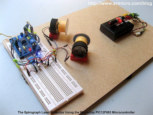
The 8 pins PIC12F683 microcontroller is one of the smallest members of the Microchip 8-bit microcontroller families but equipped with powerful peripherals such as ADC and PWM capabilities. This make this tiny microcontroller is suitable for controlling the DC motor speed. In order to demonstrate the PIC12F683 capabilities and to make this tutorial more attractive, I decided to use the PIC12F683 microcontroller to generate simple and yet fascinating laser light show from a cheap keychain laser pointer.

Building your own Simple Laser Projector

The basic of laser light shown in many entertainments club or park mostly use two method; the first one is to beam the laser shower on the spectators and the second one is to display the laser drawing pattern on the screen. On this tutorial we are going to build the laser projector that displays the spirograph pattern on the screen using the tiny Microchip PIC12F683 microcontroller.

The principle of making the spirograph laser projector is to use at least two DC motors with the attached mirror on it, these mirrors then will deflect the laser beam from one DC motor mirror to the second DC motor mirror and then finally to the screen. By controlling each of the DC motors spinning speed we could generate a fascinating laser spirograph pattern on the screen as shown on this following picture.

The best way to control the DC motor speed is to use the PWM (pulse wave modulation) signal to drive the DC Motor and because we want to change the DC motor speed manually, therefore we need to use the trimport or potentiometer to control each of the DC motors speed. Hmm, this sound like an appropriate job for the microcontroller but could we use this tiny 8 pins PIC12F683 microcontroller to handle this task?

From the datasheet you will notice that the Microchip PIC12F683 microcontroller only has one PWM output (CCP1) and four ADC input channel (AN0, AN1, AN2 and AN3). Because we need two PWM output, therefore instead of using the PIC12F683 microcontroller build in PWM peripheral, in this tutorial I will show you how to generate the PWM signal base on the PIC12F683 microcontroller TIMER0 peripheral. The following is the complete electronic schematic for the laser projector project.

Ok before we go further with the detail; let’s list down the supporting peripherals needed to complete this laser projector project:

  • Hot glue gun
  • Keychain laser pointer or any available laser pointer
  • 3xAA, 4.5 volt battery holder for powering the laser pointer, please use the same voltage rate used by your laser pointer.
  • Two DC motor taken from the discarded PS2 Dual shock joystick
  • Two toy’s car tire taken from tamiya racing car
  • CD/DVD for the mirror, use a kitchen scissor to cut the CD/DVD into the two circle shape mirror with approximately 38 mm in diameter
  • Some toys plastic bricks for holding the DC motor
  • Breadboard
  • Hardboard or acrylic is used for the base of our laser projector
  • Double Tape

The following are the electronic parts and the software development tools that I used to make this laser projector project:

  • Resistor: 330 (3), 1K (5) and 10K (1)
  • Trimport: 10K (2)
  • Capacitor: 100nF (2) and 10nF (1)
  • One 100uH Inductor
  • Two 1N4148 Diodes
  • Two Blue and one Red Light Emitting Diode (LED)
  • Two 2N2222A transistors
  • One Mini Push Button Switch
  • One Microchip PIC12F683 Microcontroller
  • Microchip MPLAB v8.46 IDE (Integrated Development Environment)
  • Microchip Macro Assembler MPASMWIN.exe v5.35, mplink.exe v4.35
  • HI-TECH C Compiler for PIC10/12/16 MCUs (Lite Mode) V9.70
  • Microchip PICKit3 Programmer (Firmware Suite Version: 01.25.20)

This project is aim as the continuing lessons to my previous posted blog Introduction to PIC Assembly Language Part-1 and Introduction to PIC Assembly Language Part-2, therefore I used the same PIC12F683 board presented in the part 2 which you could down load both of the electronic schematic and the PCB layout designed in Eagle CAD format. The other interesting feature of this laser projector project is; besides the PIC assembly code I also provide the C language version of this project for the C language lover and is compiled with the HI-TECH C Compiler (recently the HI-TECH Software has been acquired by Microchip). This C language version could be used for learning as well as the embedded system programming language comparison.

In this project I also use a new Microchip PICKit3 programmer but of course you could use the Microchip PICKit2 programmer to download the hex code to the PIC12F683 microcontroller flash.

Building your own Simple Laser Projector using the Microchip PIC12F683

The following is the Laser Projector code in PIC Assembly Language:

;******************************************************************************
;  File Name    : laserlight.asm
;  Version      : 1.0
;  Description  : Laser Light Show Project
;  Author       : RWB
;  Target       : Microchip PIC12F683 Microcontroller
;  Compiler     : Microchip Assembler (MPASMWIN.exe v5.35, mplink.exe v4.35)
;  IDE          : Microchip MPLAB IDE v8.46
;  Programmer   : PICKit3 (Firmware Suite Version: 01.25.20)
;  Last Updated : 01 April 2010
; *****************************************************************************
#include <p12F683.inc>
__config (_INTRC_OSC_NOCLKOUT & _WDT_OFF & _PWRTE_OFF & _MCLRE_OFF & _CP_OFF & _IESO_OFF & _FCMEN_OFF)
#define MAX_TMR0 0xFB
#define MAX_COUNT .200
#define MAX_DEBOUNCE 0x0A
#define MAX_TBLINDEX 0x0A
; Define variables used
     cblock 0x20
Delay:2                      ; Define two registers for the Delay and Delay + 1
mode                         ; Operation Mode
pwm_count                    ; Hold the Main PWM Counter
pwm_m1                       ; Hold the PWM width for Motor 1
pwm_m2                       ; Hold the PWM width for Motor 2
keycount                     ; Debounce Count
tableindex                   ; Table Index for Auto PWM
     endc
; Define variable use for storing STATUS and WREG register
     cblock 0x70             ; Use unbanked RAM, available both in Bank0 and Bank1
saved_w
saved_status
     endc
; Start the Light show Assembler Code here
     org 0x00                ; We always start at flash address 0
     goto Main               ; Jump to Main
     org 0x04                ; 0x04: Start PIC Interrupt Address
PIC_ISR:                     ; Start the PIC Interrupt Service Routine
     movwf   saved_w         ; Save Working Register
     movf    STATUS,w        ; Save Status Register
     movwf   saved_status
; Check the TIMER0 Interrupt here
     btfss   INTCON,T0IF
     goto    ExitISR         ; If (T0IF != 1) then Exit ISR
     bcf     STATUS,RP0      ; Select Registers at Bank 0
     incf    pwm_count       ; pwm_count++
     movlw   MAX_COUNT
     subwf   pwm_count,w     ; if (pwm_count < MAX_COUNT) then CheckPWM
     btfss   STATUS,C        ; else clear GP1 and GP2
     goto    CheckPWM
     bcf     GPIO,GP1        ; GPIO1=0
     bcf     GPIO,GP2        ; GPIO2=0
     goto    ExitPWM
CheckPWM:
     movf    pwm_m1,w
     subwf   pwm_count,w
     btfsc   STATUS,Z        ; if (pwm_count == pwm_m1) then Set GP1
     bsf     GPIO,GP1        ; Set GP1 Bit
CheckM2:
     movf    pwm_m2,w
     subwf   pwm_count,w
     btfsc   STATUS,Z        ; if (pwm_count == pwm_m2) then Set GP2
     bsf     GPIO,GP2        ; Set GP2 bit
ExitPWM:
     bcf     INTCON,T0IF     ; clear the TIMER0 interrupt flag
     movlw   MAX_TMR0
     movwf   TMR0            ; TMR0 = MAX_TMR0
ExitISR:
     movf    saved_status,w
     movwf   STATUS          ; Restore STATUS Register
     swapf   saved_w,f
     swapf   saved_w,w       ; Restore W Register
     retfie                  ; Return from Interrupt
Main:
     bsf     STATUS,RP0      ; Select Registers at Bank 1
     movlw   0x70
     movwf   OSCCON          ; Set the internal clock speed to 8 MHz
     movlw   0x39            ; GP1 and GP2 Output, GP0,GP3,GP4 and GP5 as Input
     movwf   TRISIO          ; TRISIO = 0x39        

     bcf     STATUS,RP0      ; Select Registers at Bank 0
     movlw   0x07
     movwf   CMCON0          ; Turn off Comparator (GP0, GP1, GP2)
     clrf    GPIO

; Now we Set the ADC Peripheral
     bsf     STATUS,RP0      ; Select Registers at Bank 1
     movlw   0x79            ; Set AN0 (GP0) and AN3 (GP4) as Analog Input
     movwf   ANSEL           ; Using the Internal Clock (FRC)  

; Now we set the TIMER0 Peripheral
; TIMER0 Period = 1/FSOC x 4 x Prescale x TMR0
     movlw   0x00            ; Use TIMER0 Prescaler 1:2, Internal Clock
     movwf   OPTION_REG      ; OPTION_REG = 0x00
     bcf     STATUS,RP0      ; Select Registers at Bank 0
     movlw   MAX_TMR0
     movwf   TMR0            ; TMR0=MAX_TMR0      

; Initial the variables used
     clrf    mode            ; Default mode = 0, Light Show Off
     clrf    pwm_count       ; pwm_count = 0
     clrf    pwm_m1          ; pwm_m1 = 0
     clrf    pwm_m2          ; pwm_m2 = 0
     clrf    keycount        ; keycount = 0
     clrf    tableindex      ; tableindex = 0
; Activate the Interrupt
     bsf     INTCON,GIE      ; Enable Global Interrupt
MainLoop:
     btfsc   GPIO,GP5        ; Now we check the Button
     goto    CheckMode       ; if (GP5 != 0) goto CheckMode
     movlw   0x01
     addwf   keycount        ; keycount=keycount + 1
     movf    keycount,w
     sublw   MAX_DEBOUNCE
     btfss   STATUS,C        ; if (keycount > MAX_DEBOUNCE) goto KeyPressed
     goto    KeyPressed
     goto    CheckMode       ; else CheckMode
KeyPressed:
     clrf    keycount        ; keycount=0
     incf    mode            ; mode++
     movlw   0x03
     subwf   mode,w          ; W = mode - 0x03
     btfsc   STATUS,C        ; if (mode >= 0x03)
     clrf    mode            ; mode=0;
     movlw   0x01            ; else check the mode
     subwf   mode,w
     btfss   STATUS,C        ; if (mode >= 0x01) goto TurnOn
     goto    TurnOff         ; else goto TurnOff
     goto    TurnOn
TurnOff:
     bcf     INTCON,T0IE     ; Disable TIMER0 Interrupt
     clrf    pwm_count       ; pwm_count = 0
     clrf    pwm_m1          ; pwm_m1 = 0
     clrf    pwm_m2          ; pwm_m2 = 0
     bcf     GPIO,GP1
     bcf     GPIO,GP2
     movlw   .250
     call    DelayMs         ; DelayMs(250)
     movlw   .250
     call    DelayMs         ; DelayMs(250)
     goto    CheckMode
TurnOn:
     bsf     INTCON,T0IE     ; Enable TIMER0 Interrupt                    

CheckMode:
     movlw   0x01
     subwf   mode,w
     btfss   STATUS,Z        ; if (mode == 1) goto ShowMode1
     goto    CheckMode2
     goto    ShowMode1
CheckMode2:
     movlw   0x02
     subwf   mode,w
     btfss   STATUS,Z        ; if (mode == 2) goto ShowMode2
     goto    KeepLoop
     goto    ShowMode2
ShowMode1:                   ; Used ADC for PWM
     movlw   B'00000001'     ; Left Justify and turn on the ADC peripheral, channel 0 (AN0)
     movwf   ADCON0          ; Vreff=Vdd
     bsf     ADCON0,GO       ; Start the ADC Conversion on channel 0 (AN0)
     btfss   ADCON0,GO       ; while(GO == 1)
     goto    $-1             ; Keep Loop
     call    Delay1ms
     movlw   B'00000001'     ; Left Justify and turn on the ADC peripheral, channel 0 (AN0)
     movwf   ADCON0          ; Vreff=Vdd
     bsf     ADCON0,GO       ; Start the ADC Conversion on channel 0 (AN0)
     btfss   ADCON0,GO       ; while(GO == 1)
     goto    $-1             ; Keep Loop
     movf    ADRESH,w        ; Conversion Done, Read ADRESH
     movwf   pwm_m1          ; pwm_m1 = ADRESH
     call    Delay1ms

     movlw   B'00001101'     ; Left Justify and turn on the ADC peripheral, channel 3 (AN3)
     movwf   ADCON0          ; Vreff=Vdd
     bsf     ADCON0,GO       ; Start the ADC Conversion on channel 3 (AN3)
     btfss   ADCON0,GO       ; while(GO == 1)
     goto    $-1             ; Keep Test
     call    Delay1ms
     movlw   B'00001101'     ; Left Justify and turn on the ADC peripheral, channel 3 (AN3)
     movwf   ADCON0          ; Vreff=Vdd
     bsf     ADCON0,GO       ; Start the ADC Conversion on channel 3 (AN3)
     btfss   ADCON0,GO       ; while(GO == 1)
     goto    $-1             ; Keep Test
     movf    ADRESH,w        ; Conversion Done, Read ADRESH
     movwf   pwm_m2          ; pwm_m2 = ADRESH
     call    Delay1ms
     goto    KeepLoop
ShowMode2:                   ; Used Predefined Value for PWM
     movf    tableindex,w
     call    tablepwm1       ; Call tablepwm1
     movwf   pwm_m1          ; Assigned it to pwm_m1
     movlw   .30
     call    DelayMs         ; DelayMs(30)

     movf    tableindex,w
     call    tablepwm2       ; Call tablepwm2
     movwf   pwm_m2          ; Assigned it to pwm_m2
     movlw   .30
     call    DelayMs         ; DelayMs(30)
     incf    tableindex      ; tableindex++
     movlw   MAX_TBLINDEX
     subwf   tableindex,w
     btfss   STATUS,C        ; if (tableindex >= 0x0A) then tableindex = 0
     goto    KeepLoop
     clrf    tableindex      ; tableindex = 0
KeepLoop:
     goto    MainLoop        ; Goto MainLoop
; Predefined value table for Automatic PWM
tablepwm1:
     addwf   PCL,f
     retlw   0x10
     retlw   0x5A
     retlw   0x9A
     retlw   0x20
     retlw   0x40
     retlw   0x8A
     retlw   0x82
     retlw   0x30
     retlw   0x58
     retlw   0xAA
tablepwm2:
     addwf   PCL,f
     retlw   0x70
     retlw   0x8A
     retlw   0x2A
     retlw   0x30
     retlw   0x1C
     retlw   0x2A
     retlw   0x4B
     retlw   0xA0
     retlw   0x18
     retlw   0x2A
;----------------- DelayMs: Millisecond Delay Subroutine ----------------------
; Paramater: WREG = delay amount in milisecond, max: 255 millisecond
DelayMs:
     movwf   Delay + 1
DelayLoop:
     call    Delay1ms
     decfsz  Delay + 1,f     ; Decrease Delay + 1, If zero skip the next instruction
     goto    DelayLoop       ; Not zero goto DelayLoop
     return                  ; return to the caller
;----------------- Delay1ms: 1 ms Delay Subroutine ---------------------------
Delay1ms:                    ; Total Delay: 1998 x 0.5us ~ 1 ms
     movlw   0x99
     movwf   Delay
DelayLoop1:
     decfsz  Delay,f         ; Decrease Delay, If zero skip the next instruction
     goto    DelayLoop1
DelayLoop2:
     decfsz  Delay,f         ; Decrease Delay, If zero skip the next instruction
     goto    DelayLoop2      ; Not zero goto DelayLoop2
DelayLoop3:
     decfsz  Delay,f         ; Decrease Delay, If zero skip the next instruction
     goto    DelayLoop3      ; Not zero goto DelayLoop2
     return                  ; Return to the caller
     end
; EOF: laserlight.asm

The following is the Laser Projector Project code in C Language version:

// ***************************************************************************
//  File Name    : laserlight.c
//  Version      : 1.0
//  Description  : Laser Light Show Project
//  Author       : RWB
//  Target       : Microchip PIC12F683 Microcontroller
//  Compiler     : HI-TECH C PIC10/12/16 MCUs (Lite Mode) V9.70
//  IDE          : Microchip MPLAB IDE v8.46
//  Programmer   : PICKit3 (Firmware Suite Version: 01.25.20)
//  Last Updated : 03 April 2010
// ***************************************************************************
#include <pic.h>
/*   PIC Configuration Bit:
**   INTIO     - Using Internal RC No Clock
**   WDTDIS    - Wacthdog Timer Disable
**   PWRTEN    - Power Up Timer Enable
**   MCLRDIS   - Master Clear Disable
**   UNPROTECT - Code Un-Protect
**   UNPROTECT - Data EEPROM Read Un-Protect
**   BORDIS    - Borwn Out Detect Disable
**   IESODIS   - Internal External Switch Over Mode Disable
**   FCMDIS    - Monitor Clock Fail Safe Disable
*/
__CONFIG(INTIO & WDTDIS & PWRTEN & MCLRDIS & UNPROTECT \
  & UNPROTECT & BORDIS & IESODIS & FCMDIS);
// Using Internal Clock of 8 MHz
#define FOSC 8000000L
#define MAX_COUNT 200
#define MAX_TMR0 0xFB
#define MAX_DEBOUNCE 0x0A
#define MAX_TBLINDEX 0x0A
unsigned char pwm_count=0;
unsigned char pwm_m1=0;
unsigned char pwm_m2=0;
unsigned char tablepwm1[10]={0x10,0x5A,0x9A,0x20,0x40,0x8A,0x82,0x30,0x58,0xAA};
unsigned char tablepwm2[10]={0x70,0x8A,0x2A,0x30,0x1C,0x2A,0x4B,0xA0,0x18,0x2A};
unsigned char tableindex=0;
/* The Delay Function */
#define	delay_us(x) { unsigned char us; \
			        us = (x)/(12000000/FOSC)|1; \
			        while(--us != 0) continue; }
void delay_ms(unsigned int ms)
{
  unsigned char i;
  do {
    i = 4;
    do {
      delay_us(164);
    } while(--i);
  } while(--ms);
}
static void interrupt isr(void)
{
  if(T0IF) {	       // TIMER0 Interrupt Flag
    pwm_count++;       // PWM Count Increment
    if (pwm_count >= MAX_COUNT) {
      pwm_count=0;
      GPIO1=0;         // Turn off GP1
      GPIO2=0;         // Turn off GP2
    }
    if (pwm_count == pwm_m1) {
      GPIO1=1;         // Turn On GP1
    }    

    if (pwm_count == pwm_m2) {
      GPIO2=1;         // Turn On GP2
    }      

    TMR0 = MAX_TMR0;   // Initial Value for TIMER0 Interrupt
    T0IF = 0;	       // Clear TIMER0 interrupt flag
  }
}
void main(void)
{
  unsigned char mode,keycount;
  OSCCON=0x70;         // Select 8 MHz internal clock
  /* Initial Port Used */
  TRISIO = 0x39;       // GP1 and GP2 Output, GP0,GP3,GP4 and GP5 as Input
  CMCON0 = 0x07;       // Turn off Comparator (GP0, GP1, GP2)
  GPIO = 0x00;         // Turn Off all IO
  /* Init ADC Peripheral */
  ANSEL = 0x79;        // Set AN0 (GP0) and AN3 (GP4) as Analog Input, Internal Clock
  /* Init TIMER0: TIMER0 Period = 1/FSOC x 4 x Prescale x TMR0*/
  OPTION = 0b00000000; // 1:2 Prescale
  TMR0=MAX_TMR0 ;
  /* Init Variable Used */
  pwm_count=0;
  pwm_m1=0;
  pwm_m2=0;
  mode=0;
  keycount=0;
  tableindex=0;
  GIE =1;		       // Enable Global Interrupt

  for(;;) {
    // Display the LED
    if (GPIO5 == 0) {
      keycount++;
      if (keycount > MAX_DEBOUNCE) {
        keycount=0;
        mode = mode + 1;
        if (mode > 2) mode = 0;
        if (mode >= 0x01) {
          T0IE = 1;	       // Enable TIMER0 Interrupt on Overflow
        } else {
          T0IE = 0;	       // Disable TIMER0 Intterupt on Overflow
          pwm_count=0;
          pwm_m1=0;
          pwm_m2=0;
          GPIO1=0;             // Turn off GP1
          GPIO2=0;             // Turn off GP2
          delay_ms(500);
        }
      }
    }
    if (mode == 1) {
      /* Read the ADC here */
      ADCON0=0b00000001;       // select left justify result. ADC port channel AN0
      GODONE=1;	               // initiate conversion on the channel 0
      while(GODONE) continue;  // Wait for ldr_left conversion done
      pwm_m1=ADRESH;           // Read 8 bits MSB, Ignore 2 bits LSB in ADRESL
      delay_ms(1);
      /* Read the ADC here */
      ADCON0=0b00001101;       // select left justify result. ADC port channel AN3
      GODONE=1;	         // initiate conversion on the channel 4
      while(GODONE) continue;  // Wait for ldr_left conversion done
      pwm_m2=ADRESH;           // Read 8 bits MSB, Ignore 2 bits LSB in ADRESL     

      delay_ms(1);
    }
    if (mode == 2) {
      pwm_m1=tablepwm1[tableindex];
      delay_ms(10);
      pwm_m2=tablepwm2[tableindex];
      delay_ms(10);
      tableindex++;
      if (tableindex >= MAX_TBLINDEX)
        tableindex = 0;
    }
  }
}
/* EOF: laserlight.c */

Generating the PWM (Pulse Width Modulation)


For more detail: Building your own Simple Laser Projector using the Microchip PIC12F683 Microcontroller

The post Building your own Simple Laser Projector using the Microchip PIC12F683 Microcontroller appeared first on PIC Microcontroller.

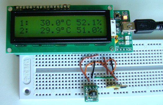
Simplest Temperature Data Logger using PIC12F683

$
0
0

Introduction
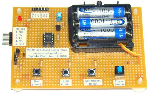
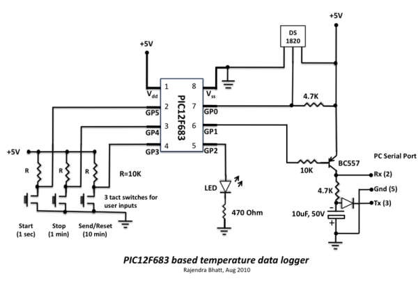
There are varieties of digital temperature logger projects available online based on different microcontrollers. The one I am going to talk about is based on a Microchip’s 8-pin microcontroller, PIC12F683. It reads temperature values from a DS1820 digital sensor and stores in its internal EEPROM. PIC12F683 has 256 bytes of internal EEPROM and we are going to store the temperature values in 8-bit format. This means only the eight most significant bits of temperature data from DS1820 will be read and as such the temperature resolution will be of 1 degree C.

Logger

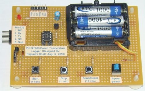
My temperature logger has following features:

  • Reads temperature from a DS1820 sensor and stores in the internal EEPROM locations.
  • Can store up to 254 temperature values. EEPROM location 0 is used to store the sampling interval, and location 1 is used to store the number of records.
  • Three sampling interval options: 1 sec, 1 min, and 10 min. This can be selected during powering up.
  • Start and Stop buttons for control operations.
  • The recorded temperature values can be sent to PC through a serial port. A separate Send button is available to initiate data transfer.
  • A LED to indicate various ongoing operations.
  • Reset button to clear all previous records.


Circuit Design
PIC12F683 has 6 I/O pins, out of which one (GP3, pin 4) is I/P only pin. Here is how we are going to assign the port pins.
The six I/O pins of PIC12F683 are assigned as follows:
1. GP0 (Pin 7, I/P): This pin will be used to read the temperature value from DS1820 sensor.
2. GP1 (Pin 6, O/P): This will be used for serial data transfer to a PC.
3. GP2 (Pin 5, O/P): LED output pin.
4. GP3 (Pin 4, I/P): Send (tactile switch)
5. GP4 (Pin 3, I/P): Stop (tactile switch)
6. GP5 (Pin 2, I/P): Start (tactile switch)

The post Simplest Temperature Data Logger using PIC12F683 appeared first on PIC Microcontroller.

Humidity and temperature measurements with Sensirion’s SHT1x/SHT7x sensors using PIC18F2550 (Part 1)

$
0
0

Temperature and relative humidity are two very important ambient parameters that are directly related to human comfort. Sometimes, you may be able to bear higher temperatures, if there is a lower relative humidity, such as in hot and dry desert-like environment. However, being in a humid place with not very high temperature may make you feel like melting. This is because if there is high relative humidity, sweat from our body will evaporate less into the air and we feel much hotter than the actual temperature. Humidifiers and dehumidifiers help to keep indoor humidity at a comfortable level. Today we will discuss about Sensirion’s SHT series of digital sensors, more specifically SHT11 and SHT75, which are capable of measuring both temperature and relative humidity and provide fully calibrated digital outputs. We will interface both the sensors to PIC18F2550 microcontroller and compare the two sets of  measurements to see the consistency between the two sensors. This tutorial is divided into two parts. The first part will cover all the details regarding the sensors, including their specification, interface, and communication protocol. The second part will be more focussed on the circuit diagram, implementation of the communication protocol with PICMicro, and the results.

Sensirion’s SHT1x

Theory

Sensirion offers multiple SHT series of digital sensors for measuring both relative humidity and temperature. The temperature is measured using a band-gap sensor, whereas the humidity sensor is capacitive; which means the presence of moisture in air changes the dielectric constant of the material in between the two plates of a parallel-plate capacitor, and hence varies the capacitance. The required signal conditioning, analog-to-digital conversion, and digital interface circuitries are all integrated onto the sensor chip. The various SHT series sensors have different levels of accuracy for humidity and temperature measurements, as described below.

SHT1x, 2x, and 7x series of humidity sensors (Source: http://www.sensirion.com)

SHT1x are available in surface mount type whereas SHT7x are supplied with four pins which allows easy connection. The SHT11 and SHT75 sensors both provide fully calibrated digital outputs that can be read through a two-wire (SDA for data and SCK for clock) serial interface which looks like I2C but actually it is not compatible with I2C. An external pull-up resistor is required to pull the signal high on the SDA line. However, the SCK line could be driven without any pull-up resistor. The signaling detail of the serial bus is described in the datasheet, which we will implement for PIC18F2550 microcontroller using mikroC pro for PIC compiler. The operating range of both the sensors is 0 to 100% for relative humidity, and -40.0 to 123.8 °C for temperature. The sensor consumes 3 mW power during measurement, and 5 μW, while in sleep mode.

The SHT11 module that I have got is from mikroElektronika. The sensor (SMD) is soldered on a tiny proto board with all the four pins accessible through a standard 0.1 inch spacing male header. The board comes with pull-up resistors connected to both SDA and SCK lines. One concern in this type of arrangement is the heat dissipated by the pull-up resistors could affect the measurements if the resistors and the sensor are close in the board. We will discuss about this issue later too. The SHT75 module from Sensirion, however, does not include any pull-up resistor for SDA line and therefore must be included externally.


For more detial: Humidity and temperature measurements with Sensirion’s SHT1x/SHT7x sensors using PIC18F2550 (Part 1)

The post Humidity and temperature measurements with Sensirion’s SHT1x/SHT7x sensors using PIC18F2550 (Part 1) appeared first on PIC Microcontroller.

Roll and Temperature sensor applications using PIC18F2550

$
0
0

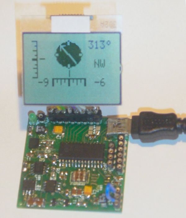
This page will show you how to use the TD-CMP modules in a way which fits you most.


Here are the technical specifications of the modules:

  • Compass: Resolution: 1° – Accuracy: 3°
  • Tilt/Roll: (TD-CMP02 and TD-CMP03 only) Resolution: 2° – Accuracy: 5°
  • Temperature: (TD-CMP03 only) Resolution= 1°C/F – Accuracy =1°
  • New: Sampling rate: 12,5 to 25 samples/second.
  • Easy Tilt/Roll calibration.(TD-CMP02 and TD-CMP03 only)
  • Interfaces: I²C, RS232 and mini-USB (as a HID device: PID=0461, VID= 1023)
  • Powered by USB bus or an external 5V.
  • Direct LCD readout possible. LCD contrast by user.
  • Low power LED lights when facing North (angle within 11,25° both left and right from North.)
  • USB Windows application (written in C#) available for free download.) Compatible with WinXp/Vista.
  • Source code (CCS C and C# .NET) and schematics (Eagle) can be purchased separately.
  • Module software is 100% upgradable with a simple bootloader.
  • PCB Dimensions: 40 x 41 mm or 1″57 x 1″61, weight: 10 grams.

Temperature sensor

These assembled modules are available from our online shop.

You may also purchase the bare pcb, a KIT DIY* version and the source code. KIT step-by-step construction guide.

New: compass calibration.

Schematics and pcb diagrams available for download. Last update: November 26, 2009.

DIY* = Do It Yourself

Power Source: JP4: Connect pin 2 to pin 3 to power the module directly from USB. Connect pin 1 to pin 2 when powered externally via JP3, pin 1.

New: Increase sampling speed from 12,5/second to 25/second: connect SPEED1 to SPEED2 (JP3, pin4 to JP3, pin2.)

LCD contrast Adjust: Connect pin 5, JP3 to +5V before powering up. Release when the desired the contrast is reached.


Tilt/Roll Calibration: (TD-CMP02 and TD-CMP03 only):

  • First place the module on a completely flat surface, power up.
  • Then shortly apply +5V (pin 1, JP2) to ADJUST (pin 5, JP3) Release after 1 second.
  • Check readings when applying tilt/roll to the module. Repeat the calibration procedure if necessary. Done.


Compass Calibration: (do not touch the PCB or chips whilst calibrating.)

  • First place the module on a completely flat surface, power up, head to North (position as shown in diagram and picture above), then turn the module slowly 360° (make 2-3 full clockwise and/or counter-clockwise spins.)
  • Now apply +5V (pin 1, JP2) to ADJUST (pin 5, JP3) Wait for 8-10 seconds; the LED will flash 3 times. Release the ADJUST pin from +5V. Power off and on.
  • Check compass readings when heading the module to N, S, E, W. Repeat the calibration procedure if necessary. Done.


Module RESET: apply GND to MCLR pin.


Temperature sensor: (TD-CMP03 only): The external LM335Z sensor connects to JP3 pin 4 and 6. No temperature will be displayed when the sensor is removed.


RS232 interface:

JP2 provides the interface to connect to your COM port and hyper terminal. Communications @ 115200 bpS, 8N1.

Use a level converter like the MAX3232 between the TD-CMP module and the pc serial port. See this example.

Also used for bootloading (module software update.) Check under the download section below for the latest version. Bootloading of the HEX-file can be done with Tiny Bootloader 1.91


For more detail: Roll and Temperature sensor applications using PIC18F2550

Current Project / Post can also be found using:

  • pic16f877a temperature projects

The post Roll and Temperature sensor applications using PIC18F2550 appeared first on PIC Microcontroller.
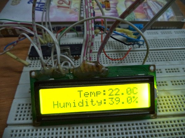
Homemade temperature LED display for PC using PIC16F876

$
0
0

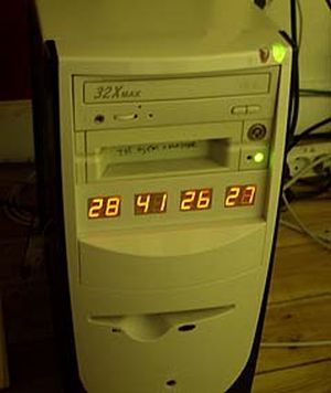
Since I started my watercooling prejoect, I have been verry interested in how well it perform,
the only way is to measure all temperatures before and after,
The motherboard temperature sensors is useless unacurate, so I’m using LM50B

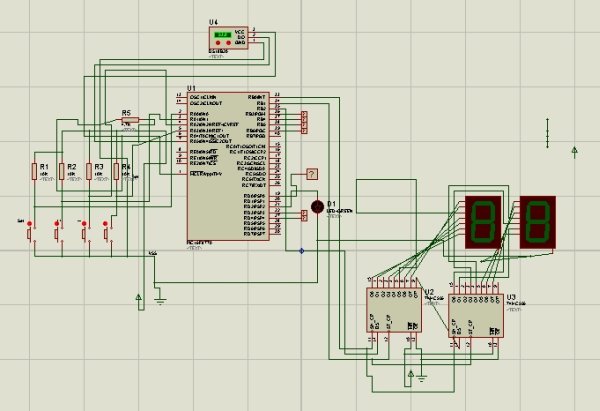
temperature LED display
By using this LM50B sensor I get 1 C of real accuracy
I use a PIC16F876 to drive a four two digits LED displays, the PIC16 has 4 analog inputs with 10 bits resolution,
now I can display 4 temperatures at the same time to monitor performance :-)
I monitor CPU, Chipset, GFX card, Harddisks.

Here is the schematic good old handdrawn original..
Here is the schematic Re-Drawn Maybe you like this better :-) OK, comments for the circuit:
You can use any number of LED displays: 2, 4, 6, or all 8, depending on how many temperatures you want to display,
LED display type must me common cathode, FET can be any N-FET type you have, I have used IRF530 I had on stock,
NPN transistors can also be used if you dont have fets, then remember to mount a 1k resistor on each base inpus.
Each sensor input connector is protected using a 1k resistor, so you can connect sensors with power on,
nothing will burn if you connect it wrong.
Only calibration requred is the refference voltage, it need to be exactly 2.5600 volt, I have used a super stable regulator,
but an LM317 can also be used to make 2.56 volt with if that is what you have. DOWNLOAD The HEX file for the PIC16F876.
The 5 volt supply is taken from a free harddrive power connector, no need to regulate it, 4.8 to 5.2 will work fine.
This complete circuit with 8 all digits consume about 100mA. Good Luck.


For more detail: Homemade temperature LED display for PC using PIC16F876

The post Homemade temperature LED display for PC using PIC16F876 appeared first on PIC Microcontroller.

Temperature controlled fan using PIC 16F877A

$
0
0

You might have come across several applications where we need to control a specific device based on analog parameter. This Embedded system works in a similar concept where we are about to control the speed of a DC motor using based on the external temperature. The rise in temperature will result in increase in speed of the motor and vice versa. These type of Temperature controlled fan systems can generally be used to maintain temperature of a room or object automatically.

Temperature controlled fan using PIC 16F877A DESIGN OF TEMPERATURE CONTROLLED FAN SYSTEM:

  • The temperature is measured by means of a temperature sensor LM35.
  • The output voltage of the sensor is fed to the A/D channel of the Microcontroller.
  • Based on the sensed temperature the speed of the motor is controlled using PWM .
  • Several temperature ranges was set in the code to vary the motor speed based on the level of temperature sensed.
  • The speed of the motor is controlled by using PWM.

Lm 35 is used to sense the external temperature which is capable of sensing temperature ranges from -55 to 150 C. The output voltage is proportional to the temperature hence there is no need of trimmers to calibrate the reading. The output voltage of this sensor varies by 10mv per degree change in temperature.

Temperature controlled fan using PIC 16F877A SchematicCALIBRATION:

We are using a 10 bit ADC and Vcc as Vref to the ADC module of the Controller. So in order to determine the step size we have to divide the Vref by our resolution that is 2^10 ( 1024 ).

Step Size = 5 / 1024 = 4.83mV

We obtain a change of 10mV with each rise or fall in temperature from the sensor. And value in the ADC register will alter by two steps with each degree change in the sensor since two increments of step size i.e 4.833mV * 2 = 9.96mV which is approximately equal to 10mV. So in order to obtain the original value we have to divide the contents in the ADC register by 2


For more detail: Temperature controlled fan using PIC 16F877A

The post Temperature controlled fan using PIC 16F877A appeared first on PIC Microcontroller.

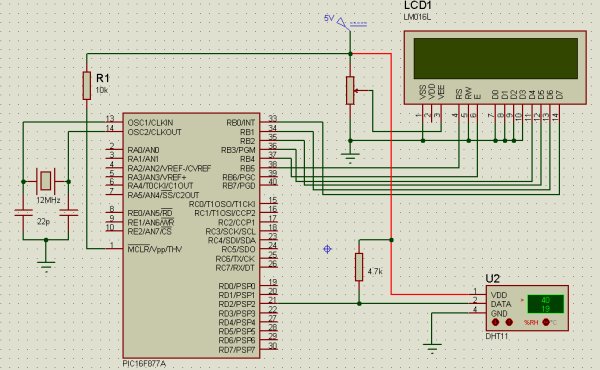
Single Chip Temperature Data Logger

$
0
0

Introduction

A data logger is a device that records measurements over time. The measurements could be any physical variable like temperature, pressure, voltage, humidity, etc. This project describes how to build a mini logger that records surrounding temperature values. It has following features:

- Uses just one 8?pin chip, so very compact size circuit.
– Temperature range: 0 to +125°C.
– Can store up to 254 measurements.
– Sampling interval options: 1 sec, 1 min, 10 min
– Reset feature to clear all previous measurements.
– Serial transfer of recorded measurements to a PC
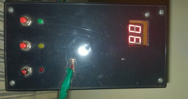
– Three tactile switches for user inputs and a LED indicator.

Single Chip Temperature Data Logger Description

The beauty of this project is that it uses just a single chip for logging. It is PIC12F683, an 8?pin microcontroller from Microchip. PIC12F683 has six general purpose I/O (GP0?GP5, GP3 is input only) pins, and 2K x 14 Flash program memory
with 256 bytes of internal EEPROM.

Temperature will be measured with a DS1820 temperature sensor. DS1820 is a one wire digital temperature sensor from Dallas Semiconductor (now MAXIM). The operating temperature range of the device is -55°C to +125°C with an accuracy of ±0.5°C over the range of -10°C to +85°C. The temperature sensor output is 9?bit Celsius temperature measurement, and so the temperature resolution corresponds to the least significant bit, and which is 0.5°C. But in this project we will use only the most significant eight bits. Therefore, the temperature resolution will be 1°C. The measured temperatures will be recorded into the internal EEPROM memory of PIC12F683.

The first location of the internal EEPROM will store the sampling interval of data logger. Sampling interval defines the time gap between two successive measurements. This project will have 3 options for sampling time: 1 sec, 1 min, and 10 min. These are user selectable. The second location of EEPROM will store the number of measurements recorded so far. And the remaining 254 EEPROM locations will store 8?bit temperatures. So, using 10 min sampling interval, 254 bytes of EEPROM will provide data logging for 42 hours. The recorded measurements can be sent to PC at any time through a serial link at 9600 baud.

User Inputs

There will be three tact switches for user inputs, namely Start, Stop, and Send/Reset. The three switches will be able to accept the following 4 user requests.

1. Start: When ‘Start’ button is pressed, data logging starts.
2. Stop: Once the ‘Stop’ button is pressed, data recording will stop.
3. Send: Transfer data to PC through serial port.
4. Reset: Holding the ‘Send’ button for 2 sec or more clears the internal EEPROM memory.

Single Chip Temperature Data Logger SchematicSampling Time Selection


The sampling interval can be selected as 1 sec, 1min, or 10 min using the same three switches. Suppose if we need 1 min sampling time, first turn OFF the power, then hold the ‘Stop’ button, turn the power ON, and wait till the LED glows. Once the LED glows, release the button, and the sampling interval will be set to 1 min. The new set sampling time will be updated to EEPROM location 0 so that in case of power failure, the previous sampling time will be restored. Similarly, use ‘Start’ and ‘Send’ buttons for 1 sec, and 10 min sampling intervals respectively.

LED Indicator

Every time the user presses input buttons, LED glows for a moment to indicate that the input is accepted. It also blinks thrice every time EEPROM Write operation takes place. It also blinks at the beginning when the power is turned ‘ON’. It also glows when the EEPROM memory is full.

For more detail: Single Chip Temperature Data Logger 

The post Single Chip Temperature Data Logger appeared first on PIC Microcontroller.
Online Monitoring of Temperature of Conductors Using Zigbee and GSM

$
0
0

Project Summary

An on-line monitoring system of temperature of conductors and fittings based on GSM SMS and Zigbee is produced in this project, by which the temperature of conductors and fittings can be monitored in real-time and some accidents caused by the increased temperature can be avoided. The principle and the feature of GSM SMS and Zigbee communication are analyzed. The construction of this system is outlined, and the force modal of calculating the variety of the sag due to the increased temperature of conductors is built. The Zigbee communication module is produced based on RF4CE standard. Finally, the software and hardware design of the online temperature monitoring unit of conductors and fittings are outlined.

Project Description

With fast development of economy in India, the demand of electricity is higher and higher, and the problem between lag of construction of network and inadequacy of transmission capacity becomes increasingly prominent, which exacerbates the unharmonious contradictions of development between power grids and power generation structure. Some provinces and cities have begun to take power limited policies to alleviate contradiction of the current electricity supply-demand, how to resolve this problem has become imperative responsibility for many power workers. Recently, in order to prevent overloading of transmission lines, domestic power system usually adopts the static, conservative transmission capacity value in design, which is a conservative static value based on the severest weather conditions.

Online Monitoring of Temperature of Conductors Using Zigbee and GSMHowever, such severe weather conditions rarely occurred, and it has resulted in the inefficient use of potential transmission capacities in most time. In the situation of “east-west power transmission, south-north power transaction, nationwide electricity interconnection”, long-distance, large-capacity and high-voltage transmission lines will be more and more. By 2010, the transmission capacity of some main lines of 500 kV will reach or exceed 1 GW. By 2020, the transmission capacity for most lines of 500 kV will reach 1 ~ 1. 5GW. Some normal current for heavy short lines will reach 2 GW, which will be near 3 GW in accidents. Now, according to the traditional technology, the transmission capacity can be increased only by adding transmission lines. However, it is becoming more and more difficult to build new transmission lines with the transmission lines increased.

From the perspective of sustainable development and environmental protection, we should pay more attention from power grids expansion to increase the potential transmission capacity of available transmission lines, and enhance the transmission capacity of power grids, so as to resolve the problems between high requirement of electricity and difficulty of new transmission line. In March 2005, the State Grids held a particular meeting about improving the transmission capacity of power grids in Beijing, the meeting pointed out that at the same time of building main electrified wire netting of super high voltage, we need actively and fully tap the potential of existing capacity. At present, some areas adopt the allowable temperature value of 70 to 80 or even 90. Properly increasing the allowable temperature of existing conductors can increase stable carrying capacity of transmission lines, thereby the normal transmission capacity is improved. The method is a breakthrough of current technical regulations, the impact caused by improving conductor temperature on conductors, the mechanical strength and the lifespan of matched fittings, the increase in sag and so on should be studied. In addition, if the conductor temperature and the sag can be real-timely monitored, the dynamic regulation of the transmission capacity, such as day and night, cloudy and sunny, summer and winter under the different environmental conditions can be realized to improve the transmission capacity. In order to meet these demands, an on-line monitoring system of temperature of conductors and fittings based on GSM SMS and Zigbee is studied and developed in this paper.

Introduction to GSM SMS, ZigBee and LM35

A. GSM SMS
GSM (Global System Mobile Communications) is a global digital mobile communication system, whose coverage is the most widely, phone owners is the largest, and reliability is very high. SMS (Short Message Service) is a kind of short message transmitted. In fact, the information transmission is achieved by receiving and sending text message in the businesses center between mobile phones and other short message carriers, and the businesses center is an independent operating system of GSM network whose main function is submitting, storing, and transferring short message. SMS is a special and important service as well as calling for users by GSM system. In this project, a self-designed industrial GSM module is selected to finish the transmission and the decoding of the monitoring data through AT command and coding of short message PDU (Protocol Data Unit).

B. ZigBee
ZigBee wireless network technology is a new standard launched and made by ZigBee Alliance. The alliance, founded in August 2001, is a fast-growing and non-profit organization, and it aims is to provide consumers with more flexible and easier electronic products. The second half of 2002, four large corporations including the British company Invensys, Mitsubishi Electric Corporation, Motorola and the Dutch giant Philips Semiconductor Corporation jointed together to announce that they would join the “ZigBee Alliance” to invent the next-generation wireless communication standards named “ZigBee”, which became a significant milestone in the development process. In October 2004, the ZigBee Alliance announced a version 1.0 of ZigBee protocol, and in December 2005 version 1.1. ZigBee uses free frequency bands of 2.4 GHz and 900 MHz, and its transmission rate is 20 kbps to 250 kbps. In this paper, the perfect chip cc2430 is selected to design the wireless hardware platforms of ZigBee, a standard ZigBee wireless network module is produced, and a reduced version of ZigBee wireless network protocol is programmed. The Zigbee module and protocol have been successfully applied to power system, medical and some other fields.

ZigBee is the set of specs built around the IEEE 802.15.4 wireless protocol. The IEEE is the Institute of Electrical and Electronics Engineers. They are a non-profit organization dedicated to furthering technology involving electronics and electronic devices. The 802 group is the section of the IEEE involved in Information technology—Telecommunications and information exchange between systems—Local and metropolitan area networks including mid-sized networks. Group 15.4 deals specifically with wireless networking (Wireless Medium Access Control (MAC) and Physical Layer (PHY) Specifications for Low-Rate Wireless Personal Area Networks (WPANs) technologies.

Network Topologies
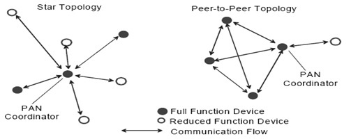
Depending on the application requirements, an IEEE 802.15.4 LR-WPAN may operate in either of two topologies: the star topology or the peer-to-peer topology. Both are shown in Figure. In the star topology the communication is established between devices and a single central controller, called the PAN coordinator.

Online Monitoring of Temperature of Conductors Using Zigbee and GSM SchematicTemperature Measurement
Temperature can be measured via a diverse array of sensors. All of them infer temperature by sensing some change in a physical characteristic. Six types with which the engineer is likely to come into contact are: thermocouples, resistive temperature devices (RTDs and thermostats), infrared radiators, bimetallic devices, liquid expansion devices, and change-of-state devices.

The Overall Structure of Online

Monitoring System
The online monitoring system of temperature of conductors and fittings based on GSM SMS and Zigbee is mainly composed of the municipal monitoring center, the communication unit, the temperature monitoring unit and the expert software, the topology of system is shown in Fig.1. The communication unit is installed on the tower with both GSM and Zigbee communication modules, and the temperature monitoring unit on the corresponding conductors with the same potential.


For more detail: Online Monitoring of Temperature of Conductors Using Zigbee and GSM

Current Project / Post can also be found using:

  • projects of temperature measurement devices
  • Temperature controller Using PIC 16f877a DS18B20 rs232
  • temperature controller using pic 18F4550
  • temperature controller using pic microcontroller project

The post Online Monitoring of Temperature of Conductors Using Zigbee and GSM appeared first on PIC Microcontroller.
PIC based wireless temperature and heartbeat read-out

$
0
0

Microcontroller based wireless temperature and heartbeat read out suitable for a operation in a small office/home environment . This system is suitable to operate with Visual LCD. Many individuals or organisations may, for various reasons,wish to use electronic surveillance technique at some time or another. This idea is to use off the shelf RF Tx/Rx modules. The weather keeps us continually occupied. Some people have even made it their profession. At home too,we like to measure all kinds of things related to our climate.That is why weather stations are available in all types and sizes.

PIC based wireless temperature and heartbeat read-out If we want to know the temperature inside and outside then purpose built indoor/outdoor thermometers are available. In the past the outside sensor of these weather stations was connected with a wire, it is now fairly standard to use RF transmission for this data. The wireless transmitters units usually make use of the 315-MHz band. These modules, once a  rare commodity, are now widely and cheaply available. In this particular discussion, we shall be using ASK(Amplitude Shift Keying) based TX/RX pair operating at 315 MHz. The transmitter module accepts serial data at a maximum of 2400bps. They are directly interfaced to a microcontroller. At the RX end, the receiver microcontroller receives the signal via the RF receiver module,decodes the serial data and reproduces the original data in the temperature and Heart Beat format.

Temperature Sensor
 Temperature is one of the fundamental physical variables in most chemical and process control applications. Accurate and reliable measurements of the temperature is important in nearby all process control applications. Temperature sensors can be analog or digital. Some of the most commonly used analog temperature sensors are : thermocouples, resistance temperature detector ( RTD)s and thermistors. Digital sensors are in the form of integrated circuits.
PIC based wireless temperature and heartbeat read-out SchematicThe choice of a sensor depends on the accuracy, the temperature range, speed of response, thermal coupling, the environment (chemical, electrical, physical) and the cost. A popular voltage output analog integrated circuit temperature sensor is LM35DZ,manufactured by National Semiconductor. This is the 3 pin analog output sensor which provides a linear output voltage of 10 mV/degree Celsius. The temperature range is 0 to 100 degree Celsius, with an accuracy of +-1.5 degree Celsius.

The post PIC based wireless temperature and heartbeat read-out appeared first on PIC Microcontroller.
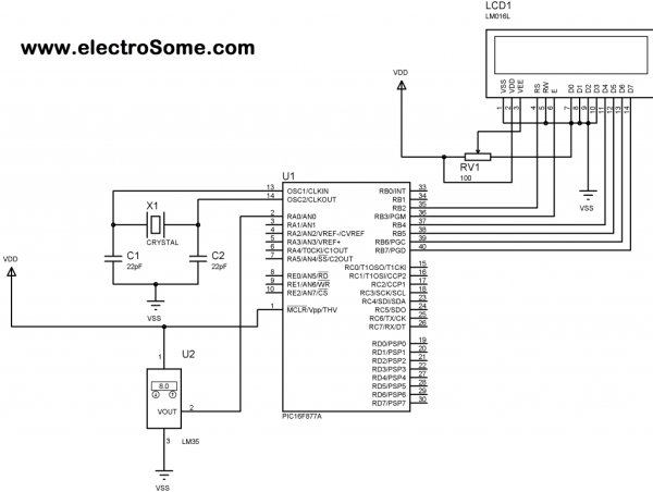
Arduino powered temperature sensing RGB LED nightlight using PICaxe

$
0
0

About a year ago I started on a project to make a temperature controlled nightlight. I was inspired by seeing these lovely LED lamps styled as mushrooms growing out of pieces of wood. Those mushrooms were made out of glass, which was somewhat beyond my skills. However I then saw some had used translucent sculpey to make mushroom nightlights on instructables. So with that discovery it seemed like it would be rather simple to do…

temperature sensing RGB LED nightlight

The first job was to solder up a three colour (RGB) LED (a super bright one from oomlout):

I then covered the LED in translucent Fimo:

As Fimo only needs to be heated to about 100C to set it’s ok to do this, as it won’t hurt the LED. Also LEDs don’t normally give out much heat, so covering them is ok. Of course this is a relatively low power (though quite bright) LED as well which helps.

I found a branch on the way home from work, which I cut up and sanded down. This formed the base for the mushroom:

As you can see I also opted for a chunky on/off button, in the style of the original mushroom lamps.

Next I put a small electronics project box into the bottom of the piece of wood and made space for a slide switch and power socket

At the time I decided to try to use a Picaxe 08m chip to control the LED and read from a temperature sensor. The Picaxe 08m has a native function to read the temperature from a DS18B20 One Wire digital temperature sensor. It also had just about enough inputs and outputs to handle controller the three colors of the LED and reading from a slide switch (to make it switch between temperature display and plain nightlight). The individual chips were also pretty cheap, so it seemed like a good plan at the time.

However the size of the circuit and number of components I needed to solder was all a bit too much for me:

temperature sensing RGB LED nightlight circuit

Eventually after much debugging I was able to get some things working – e.g. controlling the colour of the LED, but the temperature sensor just wouldn’t cooperate and always gave a high reading. I also managed to get through a few sensors due to mis-wiring them!

So I decided it was time to start again with the circuit. I bought a better soldering iron (a not too expensive digital temperature controlled one) and started on a new circuit:


For more detail: Arduino powered temperature sensing RGB LED nightlight using PICaxe

Current Project / Post can also be found using:

  • home automation pic microcontroller projects list

The post Arduino powered temperature sensing RGB LED nightlight using PICaxe appeared first on PIC Microcontroller.

Refregirator Temperature Controller Project (Save Your Electricity Bill)

$
0
0

In This Post we discuss about How to build a Refregirator Temperature Controller using Microcontroller.

This Project is Development of Thermo meter project.

Suggested Page>> MIcrocontroller Based Thermo meter project

Mainly we use Mikro C Programming Language in this Project and ISIS Proteus Software use for testing Purposes.

Refregirator Temperature Controller Project (Save Your Electricity Bill)How to Work Refregirator Temperature Controller.

You know about Refregirator has Internal Heater Coil inside the freezer Area. These heater use for melt ICE inside the freezer.Heater take lot of power units consumption for melting ICE.This is effect highly for refregirator total power consumption.We cut that extra power Units using this Refregirator Temperature controller.This project is very effective for Chest Freezer.

We placed DS18B20 Sensor inside the Refregirator and every time it measure refregirator Inside temperature on Two 7 SegmentDisplay.If Refregirator Inside Temperature reach to Preset ON Temperature and Refregirator Automatically Power On.When InsideTemperature reach Preset OFF Temperature Automatically Refregirator Power OFF.We can setup ON and OFF Temperature Using 4 Buttons.
We use Four Buttons for Setup ON/OFF Temperature in this Refregirator Temperature Controller
1) Mode Button
2) Up + Button
3) Down – Button
4) Save Button

Mode Button
Mode 1 (Press 1 time)
You Can Adjust Refregirator OFF Temperature using + and – Buttons.
You Can Save Changes using SAVE Button(Hold).

Refregirator Temperature Controller Project (Save Your Electricity Bill) SchematicMode 2 (Press Two times)

You Can Adjust Refregirator ON Temperature using + and – Buttons.
You Can Save Changes using SAVE Button(Hold).
We Should Use 4.7k Pullup Resister for DS18B20 .
This Project Succesfully Tested in Real Hardware and Work very well.


For more detail: Refregirator Temperature Controller Project (Save Your Electricity Bill)

Current Project / Post can also be found using:

  • time and temperature display usng pic microcontroller
  • life temperature measurement project
  • pic measurement of tempwrature with ethernet
  • schematic pic16f thermometer

The post Refregirator Temperature Controller Project (Save Your Electricity Bill) appeared first on PIC Microcontroller.
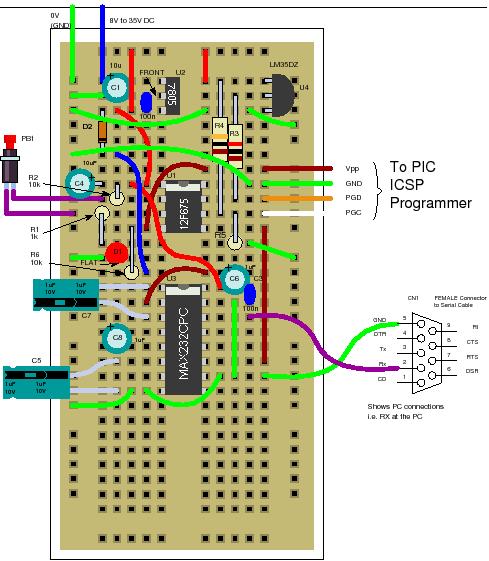
Viewing all 365 articles
Browse latest View live


<script src="https://jsc.adskeeper.com/r/s/rssing.com.1596347.js" async> </script>