The Broadcom® AFBR-S4N33C013 is a single-silicon photo-multiplier (SiPM) used for ultra-sensitive precision measurement of single photons.
The active area is 3.0 mm × 3.0 mm. A high packing density of single chips is achieved using through-silicon-via (TSV) technology and a chip-sized package (CSP). Larger areas can be covered by tiling multiple AFBR-S4N33C013 CSPs almost without any edge losses. The protective layer is made by a glass that is highly transparent down to UV wavelengths, resulting in a broad response in the visible light spectrum with high sensitivity towards blue- and near-UV region of the light spectrum.
The AFBR-S4N33C013 SiPM is best suited for the detection of low-level pulsed light sources, especially for the detection of Cherenkov or scintillation light from the most common organic (plastic) and inorganic scintillator materials (for example, LSO, LYSO, BGO, NaI, CsI, BaF, or LaBr). This product is lead-free and compliant with RoHS.
Features
High PDE of more than 54% at 420 nm
Chip-sized package (CSP)
Excellent SPTR and CRT
Excellent uniformity of breakdown voltage, 180 mV (3 sigma)
Excellent uniformity of gain
Size 3.14 mm × 3.14 mm
With TSV technology (4-side tileable), with high fill factors
KEMET, a subsidiary of Yageo Corporation (“Yageo”) (TAIEX: 2327) and leading global supplier of electronic components, announces the launch of three hybrid aluminum polymer capacitor series: A780, PHA225, and PHH225. These AEC-Q200 qualified capacitors offer a combination of highly conductive polymer technology and liquid electrolytic material in a hybrid design, resulting in an outstanding electrical performance for automotive and industrial applications. This launch aligns with the growing vehicle electrification product market, driven in part by a rising need for 48V architecture in mild hybrid electric vehicles (MHEV). According to a September 2020 report by Markets and Markets, the vehicle electrification market is projected to grow at a CAGR of 11.9% to reach USD $129.6 billion by 2025 from USD $73.7 billion.*
The A780 series is KEMET’s first release of a surface mount (V-Chip) hybrid aluminum polymer capacitor. Both liquid aluminum electrolyte and solid polymer materials are housed in a cylindrical aluminum can and when combined, provide greater advantages such as a higher ripple current, lower equivalent series resistance (ESR), lower leakage current, and exceptional self-healing capability than standard solid polymer aluminum capacitors with no liquid electrolyte. These capacitors can withstand heavy vibrations (up to 30g), meeting the stringent design requirements for automotive powertrain and industrial applications, including engine control units, DC/DC converters, 48V inverters for MHEV, switched-mode power supply (SMPS), and computer voltage regulator modules (VRM).
Further advancing hybrid aluminum polymer capacitor technology, the PHA225 and PHH225 with an axial and radial crown design also offer the same combination of highly conductive polymer and liquid electrolytic material as the A780 series. These capacitors can withstand temperatures up to 140°C, provide extremely high ripple current capability, and self-healing performance. The hybrid construction of polymer and liquid electrolytic provides extremely low and stable ESR across all temperature ranges, thus extending its operating lifetime.
Texas Instruments TPL1401 Digital Potentiometer (Digipot) offers higher load regulation in voltage-divider applications as a result of an integrated buffered wiper. The TPL1401 makes in-factory calibration and trimming easier with integrated non-volatile memory (NVM) and a simple I2C digital interface to communicate with the device. This device supports I2C standard mode (100kbps), fast mode (400kbps), and fast mode plus (1Mbps).
The Texas Instruments TPL1401 operates with either the internal reference or with the power supply as the reference and provides a full-scale output of 1.8V to 5.5V. This device also includes a wiper lock feature, a feedback (FB) pin for current-sink applications, and two bytes of user-programmable NVM space. The TPL1401 has a power-on-reset (POR) circuit that makes sure all the registers start with default or user-programmed settings using NVM. The digipot output powers on in high-impedance mode (default); this setting can be programmed to 10kΩ-GND using NVM.
Features
256-position digital potentiometer for voltage-divider applications
1 LSB INL and DNL
Wide operating range
1.8V to 5.5V power supply
–40°C to +125°C temperature range
Buffered wiper for improved load regulation
FB pin for precision current sink applications
Wiper lock function to protect from accidental writes to the digital potentiometer
Vishay introduces a new fully integrated Automotive Grade proximity and ambient light sensor for gesture recognition
Vishay introduces a new fully integrated Automotive Grade proximity and ambient light sensor for gesture recognition. Featuring Filtron technology, the Vishay Semiconductors VCNL4035X01 combines photo-detectors for proximity and ambient light, a signal conditioning IC, a 16-bit ADC, and a driver for up to three external IREDs in one compact 4 x 2.36 x 0.75 mm surface-mount package. The AEC-Q101 qualified sensor features an interrupt function and supports the I2C bus communication interface for portable electronics and smart home, industrial, and automotive applications.
Key Features
Integrated modules: ambient light sensor, proximity sensor, and signal conditioning IC
Operates ALS and PS in parallel structure
Filtron technology adoption for robust background light cancellation
Low power consumption I2C (SMBus compatible) interface
Additional Features
Integrated modules:
Ambient Light Sensor (ALS)
Proximity Sensor (PS)
Signal conditioning ICL
Operates ALS and PS in parallel structure
FiltronTM technology adoption for robust background light cancellation
Temperature compensation:
From -40 °C to +105 °C
Low power consumption I2C (SMBus compatible) interface
Output type:
I2C bus (ALS/PS)
Operation voltage:
From 2.5 V to 3.6 V
Floor life:
168 h, MSL 3, according to J-STD-020
Package type:
Surface-mount
Dimensions (L x W x H in mm):
4.0 x 2.36 x 0.75
AEC-Q101 qualified
Vishay’s VCNL4035X01’s 16-bit high-resolution ALS offers excellent sensing capabilities with sufficient selections to fulfill most applications whether dark or high transparency lens design. Both the ALS and PS have programmable interrupt features of individual high and low thresholds, which offer the best utilization of resource and power saving on the microcontroller.
Monolithic Power Systems (MPS) MP8833x Thermoelectric Cooler Controllers feature built-in internal power MOSFETs and achieves 1.5A continuous output current. These controllers include TEC current monitor, external SYNC function, and EN/SD for power sequencing. The MP8833x cooler controllers provide full protection that includes internal soft-start, Over-Current Protection (OCP), Over Voltage Protection (OVP), and Over-Temperature Protection (OTP). These controllers operate at -40°C to 125°C temperature range and 2.7V to 5.5V input voltage range. The MP8833x controllers offer 1MHz switching frequency and 2.27W QFN continuous power dissipation. Typical applications include optical laser diode modules, fiber communication networks, and systems with TEC temperature control.
Block Diagram
Features
Thermoelectric Cooling (TEC) current monitor
External SYNC function
EN/SD for power sequencing
Internal soft-star
Over-Current Protection (OCP)
Over Voltage Protection (OVP)
Over-Temperature Protection (OTP)
Specifications
1% 2.5V REF accuracy
Up to 1.5A TEC current
30mΩ internal MOSFETs for PWM switches and linear switches
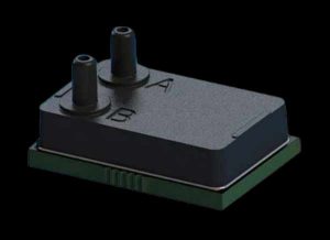
Superior Sensor Technology HV Differential Low-Pressure Sensors targets pressure ranges from as low as 0.1″ inH2O (Water Column) to 60″ inH2O with industry-leading 16-bits of resolution for each range supported. With the Multi‐Range capability enabled, optimal performance is maintained from 60″ inH2O down to even 0.1″ inH2O. The HV family employs Superior’s proprietary NimbleSense architecture that provides a very high dynamic range to enable a single device to cover the entire range of HVAC pressure requirements. Constructed with a high-reliability plastic enclosure, the components provide the ideal combination of high performance and reliability while ensuring users have a high volume cost-effective solution optimized for their HVAC requirements.
Features
Highly integrated sensor with ADC and DSP
Selectable pressure range from 0.1 to 60 inH2O
Integrated 50/60Hz notch filter
Selectable bandwidth filter from 0.1Hz to 10Hz
Very high accuracy, ±0.1% of the selected range
-20°C to +85°C operating temperature range
Long term stability, ±0.1% FSS
Temperature-compensated, 0°C to +50°C
Supply voltage compensation
Fully integrated compensation math
Standard I2C and SPI interface
For added performance, the HV Series incorporates a 50/60Hz notch filter to minimize the impact of power noise spikes. The sensors combine an advanced piezoresistive sensing element with integrated amplification, ADC, DSP, and digital interface which simplifies user integration efforts. The incorporation of advanced digital signal processing enables greater functionality thus simplifying system development, manufacturing ease, and increased reliability.
Vishay Semiconductors K857PE Si PIN Photodiode is a 4-quadrant photodetector with a 1.6mm2/quadrant active area available in a surface-mount package. This photodiode functions in epitaxial technology and offers high photosensitivity. The K857PE pin photodiode operates at -40°C to 110°C temperature range, 20V reverse voltage, and 1nA dark current. This photodiode offers 1.3V maximum forward voltage, 840nm peak sensitivity wavelength, and 30ns rise time and fall time.
Features
Surface-mount package type
Epitaxial technology
AEC-Q101 qualified
High photosensitivity
Specifications
20V reverse voltage
-40°C to 110°C operating and storage temperature range
1nA dark current
1.3V maximum forward voltage
840nm peak wavelength
30ns rise time and fall time
260°C soldering temperature
VEMD8081 Silicon PIN Photodiode
Vishay Semiconductors VEMD8081 Silicon PIN Photodiode offers high speed and enhanced sensitivity for visible light. The VEMD8081 Photodiode provides a low profile surface-mount device (SMD), including the chip with a 5.4mm2 sensitive area detecting visible and near-infrared radiation.
The Vishay Semiconductors VEMD8081 Silicon PIN Photodiode features an angle of half sensitivity ±65°, a 350nm to 1100nm range of spectral bandwidth, and a forward voltage of 2.3V to 3.3V. The VEMD8081 Photodiode is designed for high-speed photodetectors and wearables.
Diodes Incorporated has announced a family of automotive-compliant, two-wire unipolar (AH323xQ/4xQ) and latch (AH327xQ/8xQ) switch integrated circuits (ICs) that provide high sensitivity and high stability over wide operating voltage and temperature ranges. The ICs are for use in automotive proximity- and position-sensing applications, including seatbelt buckle, power window, gear selector and seat position. The adoption of two-wire hall switches reduces the number of wires required in the harness, saving on system complexity and cost while improving robustness to electrical noise.
The AH324xQ and AH328xQ have integrated self-diagnostics which continually monitor the main device blocks, supply voltage, and temperature. There is a third output state that warns of an abnormal condition. These devices are ISO 26262 ASIL-B ready, having been developed using rigorous design processes with safety analysis conducted in accordance with the ISO 26262 standard.
Diodes adopted an advanced chopper-stabilized design, which provides superior stability of the magnetic operating and releases points (BOP/BRP) over the 2.7V to 27V operating voltage and -40˚C to +150˚C temperature range. This stability, coupled with a high ESD rating of 8kV, built-in reverse blocking diode, and supply pin Zener clamp, enables the AH32xxQ series to meet the demanding requirements of automotive proximity/position-sensing applications.
When it comes to industrial PC motherboards, we all know ASRock has successfully launched some of the popular products. After the release of the ASRock iBOX 1100 rugged mini-PC, several months in, we saw the NUC 1100 Box Series mini-PCs powered by the 11th Generation Intel Core i7/i5/i3 processors and Iris® Xe graphics a couple of months back. The NUC 1100 Box Series came in three models – NUC BOX-1165G7, NUC BOX-1135G7, and NUC BOX-1115G4. ASRock has now announced Tiger Lake-based STX-1500 (Mini-STX), and IMB-1224 (Mini-ITX).
This is a mini-STX form factor motherboard based on an Intel Tiger Lake-UP3 MCP processor that comes in three CPU variants clocked at different frequencies supporting dual-channel DDR4 64GB memory. The graphics are also Intel Iris Xe for the i7 and i5 CPUs while Intel UHD graphics for i3 CPU. One of the important features in video output is the support for Quadruple display is provided via HDMI, eDP, and LVDS interfaces.
STX-1500 specifications:
SoC: Intel 11th Gen (Tiger Lake-UP3) Core Processors, up to 28W TDP
STX-1500P: Intel i7-1185G7E clocked up to 2.8GHz
STX-1500M: Intel i5-1145G7E clocked up to 2.6GHz
STX-1500V: Intel i3-1115G4E clocked up to 3.0GHz
Memory: Support dual channel DDR4 3200 MHz with 64GB (32GB per DIMM)
Socket: 2x 260-pin SO-DIMM
Graphics: Intel Iris Xe Graphics for i7/i5 CPU / Intel UHD Graphics for i3 Processor
Video output:
HDMI 2.0a with maximum resolution up to 4096×2160 at 60Hz refresh rate
LVDS dual-channel 24-bit up to 1920 x 1200 at 60Hz refresh rate
eDP 1.4 with max resolution up to 4096×2304 at 60Hz refresh rate
Audio: 2 (Mic-in, Line-out)
Expansion: 1x M.2 with PCIe x1, USB 2.0 and CNVi for Wireless or 1x M.2 with PCIe x1 / USB 3.2 / USB2.0 and SIM for 4G/5G
USB: 3x USB 3.2 Gen2, 5x USB 2.0
Power Supply: 12~28V DC-In with 4-pin wafer PWR cable or DC Jack
Temperature sensors, alone, or on their own, have infinite applications, however, one of the challenges typically experienced with their use is the varying degree of accuracy obtainable with the sensors available in the market. Adding to the growing list of precision temperature sensors in the market, Austria based sensor manufacturer ASM AG recently introduced the AS6221 temperature sensor.
The AS6221 is a highly accurate digital temperature sensor with accuracy levels of up to 0.09 °C, which is around the usual ideal accuracy level desired for applications that require high-performance thermal information.
A complete digital sensor system, the AS6221 requires no calibration or linearization and comes in an ultra-small form factor (WLCSP 1.5 x 1.0 mm) that enables accurate body/skin temperature measurements in health and lifestyle monitoring products. Design with the current standards in mind, in addition to the high accuracy and the small form factor, the AS6221 also offers very low power consumption which makes it ideal for battery-based applications, with a current consumption of around 6μA for 4 samples per second (SPS) measurement.
AS6221 has 4 different automatic data acquisition modes and communication with connected MCU is over dedicated I2C interfaces.
Some highlight features of the sensor include:
High-temperature accuracy of ±0.09 °C (20…42 °C)
Ultra-low-power consumption: 6 µA at 4 SPS (typ.) and 0.1 μA in standby (typ.)
Small form factor WLCSP package: total size 1.5 × 1.0 mm
No calibration or linearization required
A fully-digital system with up to eight I²C addresses
Programmable Alert OUT pin:
No need to constantly poll the sensor
Best-in-class accuracy
Space-saving with ultra-small integration size
Superior power efficiency for better battery endurance
Easy-to-use solution for fast go-to-market
Enables multi-device application development
Easy to integrate with a standard serial bus connection
Alert functionality for advanced system power reduction
The application of the S6221 cuts across all fields including medical, wearables, mobile health, fitness trackers, and all sort of electronic devices.
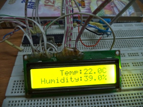
After interfacing the DHT11 with Arduino uno board at the following post: ARDUINO Humidity & Temperature Measurement Using DHT11 Sensor
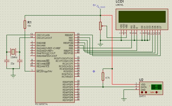
Now we are going to see how to interface this sensor with microchip pic16f877a.
There are some descriptions of how this sensor work in the above link
A brief description of the code:
The code is written using MikroC compiler.
First we must send a start signal to the sensor, we do that by configuring the pic pin connected to the sensor as output, the mcu sends 0 for 18ms then sends 1 for 30us.
After sending start signal to the sensor, the sensor will send a response signal to the mcu. To detect this signal mcu pin must be configured as input.
When the sensor finishes the response signal, it begins sending humidity and temperature data serially.
If there is a problem with the sensor or there is no sensor connected to the circuit, the LCD displays “there is no response from the sensor”. And if there is a problem in the sensor which means the values are incorrect the LCD displays “Check sum error”.
// LCD module connections
 sbit LCD_RS at RB5_bit;
 sbit LCD_EN at RB4_bit;
 sbit LCD_D4 at RB3_bit;
 sbit LCD_D5 at RB2_bit;
 sbit LCD_D6 at RB1_bit;
 sbit LCD_D7 at RB0_bit;
 sbit LCD_RS_Direction at TRISB5_bit;
 sbit LCD_EN_Direction at TRISB4_bit;
 sbit LCD_D4_Direction at TRISB3_bit;
 sbit LCD_D5_Direction at TRISB2_bit;
 sbit LCD_D6_Direction at TRISB1_bit;
 sbit LCD_D7_Direction at TRISB0_bit;
 // End LCD module connections
 char *text,mytext[4];
 unsigned char  a = 0, b = 0,i = 0,t1 = 0,t2 = 0,
               rh1 = 0,rh2 = 0,sum = 0;
 void StartSignal(){
 TRISD.F2 = 0;    //Configure RD2 as output
 PORTD.F2 = 0;    //RD2 sends 0 to the sensor
 delay_ms(18);
 PORTD.F2 = 1;    //RD2 sends 1 to the sensor
 delay_us(30);
 TRISD.F2 = 1;    //Configure RD2 as input
  }
 void CheckResponse(){
 a = 0;
 delay_us(40);
 if (PORTD.F2 == 0){
 delay_us(80);
 if (PORTD.F2 == 1)   a = 1;   delay_us(40);}
 }
 void ReadData(){
 for(b=0;b<8;b++){
 while(!PORTD.F2); //Wait until PORTD.F2 goes HIGH
 delay_us(30);
 if(PORTD.F2 == 0)    i&=~(1<<(7-b));  //Clear bit (7-b)
 else{i|= (1<<(7-b));               //Set bit (7-b)
 while(PORTD.F2);}  //Wait until PORTD.F2 goes LOW
 }
 }
 void main() {
 TRISB = 0;        //Configure PORTB as output
 PORTB = 0;        //Initial value of PORTB
 Lcd_Init();
 while(1){
 Lcd_Cmd(_LCD_CURSOR_OFF);        // cursor off
 Lcd_Cmd(_LCD_CLEAR);             // clear LCD
  StartSignal();
  CheckResponse();
  if(a == 1){
  ReadData();
  rh1 =i;
  ReadData();
  rh2 =i;
  ReadData();
  t1 =i;
  ReadData();
  t2 =i;
  ReadData();
  sum = i;
  if(sum == rh1+rh2+t1+t2){
  text = "Temp:  .0C";
  Lcd_Out(1,6,text);
  text = "Humidity:  .0%";
  Lcd_Out(2,2,text);
  ByteToStr(t1,mytext);
  Lcd_Out(1,11,Ltrim(mytext));
  ByteToStr(rh1,mytext);
  Lcd_Out(2,11,Ltrim(mytext));}
  else{
  Lcd_Cmd(_LCD_CURSOR_OFF);        // cursor off
  Lcd_Cmd(_LCD_CLEAR);             // clear LCD
  text = "Check sum error";
  Lcd_Out(1,1,text);}
  }
  else {
  text="No response";
  Lcd_Out(1,3,text);
  text = "from the sensor";
  Lcd_Out(2,1,text);
  }
  delay_ms(2000);
  }
  }
This is just an example to show how to interface 16×2 lcd with pic16f877a. The lcd is going to display “PIC16F877A” in the the first line and “LCD Example” in the second line. The code is written using MikroC compiler.
// LCD module connections
sbit LCD_RS at RB5_bit;
sbit LCD_EN at RB4_bit;
sbit LCD_D4 at RB3_bit;
sbit LCD_D5 at RB2_bit;
sbit LCD_D6 at RB1_bit;
sbit LCD_D7 at RB0_bit;
sbit LCD_RS_Direction at TRISB5_bit;
sbit LCD_EN_Direction at TRISB4_bit;
sbit LCD_D4_Direction at TRISB3_bit;
sbit LCD_D5_Direction at TRISB2_bit;
sbit LCD_D6_Direction at TRISB1_bit;
sbit LCD_D7_Direction at TRISB0_bit;
// End LCD module connections
char *text;
void main() {
TRISB = 0;
PORTB = 0;
Lcd_Init();
Lcd_Cmd(_LCD_CURSOR_OFF);        // cursor off
Lcd_Cmd(_LCD_CLEAR);             // clear LCD
text = "PIC16F877A" ;
Lcd_Out(1,4,text);
text = "LCD Example";
Lcd_Out(2,4,text);
while(1);                     //infinite loop
}
Now, I’m going to work with real time clocks, for that I will use the integrated circuit DS1307serial real time clock. I will use this ic with Arduino uno board and also I have to return to the pic microcontroller chip PIC16F877A. For the pic mcu I will use Microc and the full codes and schematics will be available on the next posts.
The DS1307 provides clock and calender. The clock shows seconds, minutes and hours and the calender shows day, month and year. The ds1307 uses I2C serial interface to transfer information with the microcontroller. More information in its datasheet.
BLDC (brushless dc) motors are three phase dc motors, unlike the simple dc motors the bldc motors are more difficult to control. These motors are used in many applications for examples rc airplans and rc cars.
In this post we will see how to control cd-rom sensored BLDC motor using Arduino uno board. But first there are some things we should know in order to control the motor in easy way.
The bldc motor that we are going to use is sensored via hall effect sensors (position sensors) attached with the motor(3 sensors). Each sensor outputs digital high for 180 electrical degrees and low for the other 180 electrical degrees.these sensors are used to tell us where is the position of the motor, then when we know the position of the motor we will energize just tow windings (of three). The below figure shows how sensors outputs and the corresponding voltage applied to the motor:
Alliance Memory 2Gb, 4Gb, and 8Gb LPDDR4 SDRAMs Offer Low Power Consumption to Increase Battery Life in Mobile Electronics; Devices Combine Low-Voltage Operation of 1.1V With Fast Clock Speeds of 1.6GHz for increased Efficiency and Performance
The 2Gb AS4C128M16MD4-062BAN, 4Gb AS4C256M16MD4-062BAN and AS4C128M32MD4-062BAN, and 8Gb AS4C256M32MD4-062BAN provide lower power consumption and faster speeds than the previous-generation LPDDR3 SDRAMs. The devices are available in 200-ball FBGA packages.
The devices offer low-voltage operation of 1.1V/1.8V to prolong battery life in portable electronics for the consumer and industrial markets. For higher efficiency for advanced audio and high-resolution video in embedded applications, the LPDDR4 SDRAMs provide clock speeds of up to 1.6GHz for high transfer rates of 3.2Gbps. For automotive applications, the AEC-Q100 qualified products can operate over an extended temperature range of -40°C to +105°C.
The LPDDR4 SDRAMs are organized as 1 channel (AS4C128M16MD4-062BAN and AS4C256M16MD4-062BAN) and 2 channels (AS4C128M32MD4-062BAN and AS4C256M32MD4-062BAN) per device. Individual channels consist of eight banks of 16 bits. The components feature fully synchronous operation; programmable read and write burst lengths of 16, 32, and on the fly; and selectable output drive strength. An integrated temperature sensor controls the self-refresh rate.
Alliance Memory’s LPDDR4 SDRAMs have been developed to provide a reliable drop-in, pin-for-pin-compatible replacement for numerous similar solutions in high-bandwidth, high-performance memory system applications — eliminating the need for costly redesigns and part requalification.
Texas Instruments TLV767 Precision Positive Voltage Linear Regulators are a wide input linear voltage regulator that supports an input voltage range from 2.5V to 16V and up to 1A of load current. The output range is from 0.8V to 6.6V or up to 13.6V in the adjustable version. Additionally, the TLV767 has a 1% output accuracy that can meet the needs of low voltage microcontrollers (MCUs) and processors.
The TLV767 is designed to have a much lower IQ than traditional wide-VIN regulators, thus making the device well positioned to meet the needs of increasingly stringent standby power requirements. When disabled, the TLV767 draws only 1.5µA of IQ. The internal soft-start time and fold-back current limit reduce inrush current during startup, thus minimizing input capacitance.
Nanotechnology company NTS Innovations says it has achieved a major milestone in its development of a graphene energy harvesting (GEH) clean energy source that can operate in any environment.
GEH is the act of harvesting energy at the nanoscale level from the naturally occurring oscillations in graphene. Freestanding graphene converts ambient energy into mechanical energy in the form of ripple fluctuations, much like waves on the ocean, says the company. Now, in partnership with the University of Arkansas, the company says it has completed the development of its energy harvesting circuit on a silicon wafer.
GEH is a nanoscale device on a semiconductor wafer,” says Preston Carter, Chief Technology Officer at NTS Innovations. “The technology itself varies slightly with temperature but is otherwise robust in all environments. GEH can generate power in outer space and aerospace environments, GEH will work anywhere on Earth, and will continue to work deep in the ocean. The only environmental limitations to GEH will be the packaging used to contain it.
With the development of an energy harvesting circuit complete, the company says it is now moving on to prototypes and optimization for commercial applications. GEH chips are made with common semiconductor manufacturing techniques, making them cost-effective, scalable, and easy to mass produce. The first generation GEH chip is targeted for 10 mW (milliwatts) with a chip size of 12 x 12 x 3 mm.
A smart control knob and pan designed for the absent-minded chef! The Smart-O-Pan takes the constant vigilance out of your culinary creations, making cooking bdddoth simple and safe.
Figure 0. Handle, Pan, and Hotplate Together
I designed the smart-o-pan with people like my mom in mind. I was the family chef for a number of years but since attending university, she’s taken over as house cook. Learning how to cook can be difficult and my mom’s tendency to start multiple other tasks while food is on the stove causes several small kitchen fires annually.
All joking aside, unattended cooking is one of the leading cause of house fires in the United States. This project ideas could help make a dent in that statistic while also making cooking easy and fun for new and learning chefs.
High level design:
General Overview, High Level Diagram
Figure 1: Overall Project Block Diagram
Overview:
The project has two main hardware functional blocks, the pan and the knob. The pan contains a sense element board and a radio transmitter connected to the PIC32. The sense element board reads a K-Type thermocouple inside the stovetop pan. This temperature reading is transmitted the knob hardware with an Xbee radio. These two blocks communicate wirelessly because in the long term I would like to have them operate independently as a pan and knob.
The knob hardware receives that radio transmitted temperature value and outputs a PWM value to a servo. This servo rotates a knob on a hotplate or conventional stove. The knob hardware continuously adjusts this temperature such that the pan levels off at a consistent user set temperature. When food on the pan cooks it evaporates much of its water. The high specific heat of water makes the pan easier to heat, leading to runaway boiling or burning. This system seeks to provide constant temperature to the pan by dynamically changing the applied temperature.
The Xbee Radios use the UART communication protocol to communicate with their respective PICs and SPI to communicate with the temperature sensor.
Background Math:
PID Control System
I made heavy use of PID control principles for controlling the temperature of the pan. Most of the material regarding PID has been explained in heavy detail during lab 4. However, I will highlight the basics of PID and the key differences between PID control of the 1DOF helicopter and PID control of a pan here.
PID Control stands for Proportional Integral Differential Control. It works by finding a proportional, integral and derivative term of an error function to minimize the error function in an unknown dynamical system.
What this means from an implementation standpoint is that PID works by finding a mapping between a sensor value/Desired value and an actuated output that influences the sensor reading. This makes more sense in the context of a project, so I’ll use this one as an example.
In this project, T(t) is a vector representing the temperature of the pan over time, D represents the desired temperature that we command the pan to reach and PWM(t) represents the equivalent pulse width output duty cycle from the microcontroller. That duty cycle turns a stove knob, thus adjusting the temperature to a value closer to the desired temperature.
In the project context, we can define our error function as the difference between the desired temperature and the initial temperature.
This PID function can be broken down into a weighted sum of terms.
The terms Kp, Ki, and Kd represent derivative, integral and proportional gain terms. These terms effectively convert the different components of the error function into the actuator/control value. If you remember dimensional analysis from physics or chemistry, these constants are useful to think of in their respective units for your specific application as sanity checks (i.e. my Kp = °C/Degree of Servo Rotation).
Modeling Pan Heat Dissipation:
My original goal was to determine the temperature at the center of a pan without invasively drilling into it. I attempted to do this by guessing the central temperature of the pan from peripheral thermocouple measurements. This required an estimator using some cylindrical solution to the basic heat equation. In an independent design project, I would consider revisiting this methodology because It has the potential to modularize the custom-made pan into a pan handle that can be attached to any pan rather than tied to one.
A professor recommended this model for dissipation in a cylinder heated by a smaller cylinder.
Figure 2: Cylinder subject to a temperature gradient
Where are simply temperatures at different radial points from the center of the bottom of our pan in this case. Therefore, knowing the temperature at two separate radial points allows us to predict the central temperature.
There are several good mathematical models for such a measurement. The shell balance approach with the resultant model makes the most sense to me. The full mathematical basis for this model can be found here.
Use of XBees rather than Bluetooth Communication
In retrospect, Bluetooth would have been a much more useful communication method between the pan and handle. Radio Communication’s biggest advantage is that it can communicate over very long distances, but it suffers more from interference than other types of communication. During testing, I noticed that I would lose packets in the lab that I wouldn’t have lost in the Baja office. I didn’t have the time to order new components after this initial purchase, but in an independent study or long term project, I would use entirely Bluetooth communication.
Logical Structure & Pictures:
It might be easy to understand the project by breaking up the functions in software between the pan and handle and illustrating how a single temperature measurement “flows” to an actuator PWM command.
Figure 3. A shortlist of the division of tasks between the handle hardware and the knob hardware.
Figure 3.5 Flow of Command from Data Reading to PWM Output. This loop repeats with a 500 mS delay.
Tradeoffs:
Internal/External Hotplate Control:
In the original project, I wanted to attach the PIC to the hotplate internally rather than via a knob. The idea was to use controllable digital potentiometers hooked up to high power transistors that spliced into the control circuitry of the hotplate. This would act as a digitally controllable knob on the inside of the device without any moving parts. However, these power transistors frequently broke down and required special connections. Therefore, I decided instead to physically rotate the knob from the outside using a servo motor instead.
Drilling into the Pan vs. Mathematical Modeling
I had also intended for the handle of the pan to be significantly more modular. Such that the pan could slide off of one pan and onto any other pan easily. Using two thermocouples, and our model before we could guess the temperature in the center of the pan non-invasively.
However, this too was problematic. Early testing gave unreliable results. Ultimately, drilling into the underside of the pan was the only way to get temperatures consistent with observation.
IEEE, ISO, ANSI, DIN/ Other standards.
No relationship either than the use of ubiquitous communication protocols. (SPI and UART)
Patents, Copy writes and Trademarks:
Use of Xbee, Sparkfun and Adafruit components for coursework only. This a permitted use case by the three websites. Not intended for use for profit or personal gain.
Design:
Software Design:
Given the breakdown of tasks in the Logical Overview Section, we can now get into thread specifics and software implementation specifics.
PID in the ISR:
I ran a standard implementation quite similar to that of lab04. To get less jitter from the derivative term, I implemented a moving average filter for the derivative error function. The temperature controller experiences a slight amount of oscillation about the set value due to a combined latency from transmitting temperature data and the thermal lag when the value on the hotplate is changed. This control function in placed in the ISR to keep control scheduled unlike other less time dependent functions.
Other considerations needed to be taken in software as well. I used an area under the curve method for calculating I, and the subtraction of two subsequent values to calculate the derivative. I took 10 samples of the derivative term to make for smoother control.
Safety Logic:
If the temperature exceeds a safety value, the stove turns off by setting the User Set Value to zero. I set that safety value to 182°C because it is the point at which lard begins to smoke. This is the minimum temperature that can result in an oil fire and is outside the necessary temperature range of any typical stovetop dessert. This logic runs in the main method because I didn’t want to write over the user set temperature variable from another thread.
UART Xbee Communication
I ran the UART initialization in main with a 9600-baud rate. I followed a guide that used RB5 TX and RB1 as the RX for the transmission. Plib has several useful UART methods to transmit single bytes. I converted my temperature values to strings before sending each individually so that I could use the Plib functions that work with char datatypes. I iterate through each char of the transmit string with a string pointer writing each individually. In reception/transmission, there is an interrupt flag in the ISR designed to only edit the store and receive buffer when the buffer is empty/full. I was only sending data from the handle to the knob in one direction, so I only needed to implement a one directional “baby monitor” system.
SPI Communication with the Bluetooth Board and the Temperature Board
I used SPI Channel 2 for both boards because I had used that setup in the past. I used framed SPI to communicate with each device. Each PIC has only a single SPI device, so directly controlling the Chip select line for each device doesn’t interfere with communications. I developed the SPI communication code from an example on the course website where communication occurs in the ISR. This loads my ISR pretty heavily and ideally, I’d like to put SPI communication somewhere else but racing to implement this element of the project during a busy week took more time than expected. I didn’t notice any extreme delays by putting SPI communications in the ISR, but It could be done better with more time. I’ll consider this outlet in my independent study.
PWM generation in the ISR:
PWM runs in the ISR because it needs to happen as close to real time as possible. Delays and interrupts from other threads could cause the PWM to delay and therefore output an incorrect value. I used the RB9 pin to output PWM control similar to the implementation in lab04. This required a little initialization in the main method, but otherwise ran completely in the ISR.
TFT Display for Testing: PT DISPLAY THREAD
I ran the TFT Display in its own thread and displayed the desired temperature, the set temperature and the current transmitted temperature value. This can run in its own thread because it only displays but doesn’t modify any of the values that the main method or the ISR need to operate. Additionally, I displayed the P,I and D coefficients so that we can tune the control values during usage. This made for much easier debugging and tuning.
Figure 5. TFT Display during operation
Hardware Design:
Hardware Overview:
Figure 6: Original Board Pinout Plan
PWM Output:
PWM Level Shifter:
The PIC only supplies 3.3V logic, and therefore can only supply a servo with 3.3V amplitude PWM. This causes the servo to jitter about instead of moving to a controlled value. This circuit upshifts that value by draining a 5V line in sync with the rising/falling PWM. The two resistors simply limit current flow from power lines.
Figure 7. Level Shifter Schematic
A good way to think about how this circuit works is to notice that It is just effectively a common base amplifier of for the PWM. The base is held at +3.3V when the input is high (also +3.3V) and the transistor is off. This allows the collector to float up to the +5V rail.
When the input goes low, the transistor turns on hard and pulls the collector to just above the logic low level of the input. Note that all of the sinking output current goes through the input pin.
I built a version of the above schematic on a breadboard to shift the level of the PWM to 5V so that the servo motor could read the PWM that the PIC could supply.
Figure 8. Level Shifter Constructed on Breadboard
Figure 9. Pan Handle Hardware Realization
Figure 10. Knob Hardware Realization
Problems and Lessons:
The biggest problem that I ran into was not accurately estimating how long hardware projects take. I’m much more of a theoretician by background, so for example imagining that a board layout would take about an hour was misguided. I also allotted myself about half a week to implement each communication protocol that I used. However, ironing out mistakes in those protocols or even just getting the correct pins to turn on takes days of consistent work. I wish I had planned for that length of time in advance and maybe scaled back a design feature to make the rest of the system function more smoothly.
I also had huge problems with power supplies. I wanted to power both circuits off of two independent 9V batteries so that they could be standalone products. I didn’t want to blow through a package of 9V batteries during debugging, so I bought a 9V supply offline without checking it’s polarity. I followed a false lead, which unfortunately baked several power supplies and a pair of components due to an incorrectly hooked up regulator. This could have been avoided with a second pair of eyes and more careful unit testing of components.
I also had problems integrating all of the individually implemented component boards together because of pin usage conflicts. The larger knob board took some creative allocation because so many of the pins are taken up by the TFT, Bluetooth module and UART channels for the XBee. When I was trying to integrate all of the individual components together, the pins needed to shift around. This caused issues with all previous bricks of code that I had written and took several days to debug. All of which could have been fixed by walking through my planned pin allocations with the TA’s earlier.
Design Results:
Several of the individual subsystems of the system worked but never at the same time. I was able to sample temperature, independently send and receive strings of data between PICs and communicate a user set temperature over Bluetooth from my phone. However, getting these functions to work all at once is another beast entirely.
I made a functional chimera board of the temperature sensor and PWM hardware for testing early on, and had a lot of promising results. This board would simply sample temperatures and output PWM.
PID control worked really well and I was quite proud of it. I think engineers generally have to build something a second time before they can reason about higher levels of functionality. The long delay time between temperature reaching the set value is dominated by the physical propagation of heat from the burner to the pan, so even with half a second waiting times between PID samples the response is very smooth and the delay is immeasurable.
The value that I would set the pan to also was quite accurate and constant to within a degree Celsius. The safety feature worked well too. I tried an experiment early on where I had some water boil and evaporate in the pan, and it quickly responded to the runaway temperature condition once the water had boiled down to a small layer. This feature should really improve safety for the user when I can fully implement the project.
The pivot from internal hotplate controls to an external knob also improved safety for the developer. Playing with the internal circuitry of a hotplate can lead to high power shocks through the body, which isn’t really ideal. Working with an external knob powered by a servo motor is both safer and simpler.
The setup could interfere with other radio communication designs because the Xbee radios could interfere with other similar radio hardware. In the next incarnation of the project, Ill be moving away from the XBees to an all Bluetooth system. Projects that use the 802.11 and 802.15.4 standards also could see packet loss due to this project because they operate in the same 2.4 GHz range. Xbee transmitter/receivers are FCC approved and licensed to work in the hobbyist 2.4GHz range. (source)
I also think that the design will be very usable, and is semi-useable now. Even though all of the individual components are broken out on breadboards, attaching the knob is really all that you have to do once the tuning is taken care of. The project would be great for anyone who tends to forget things on the stove, or those that for one reason or another can’t operate knobs on stoves easily.
Conclusion:
I’m quite proud of the components of the project that ended up working, especially temperature logging and PID. I didn’t get everything working as I had planned, but I think I’ve learned more from this project than in any individual theory based class. Every mistake and success gives you immediate feedback, so the data rate of new learned information is massive.
I struggled the most with systems integration. I did the project methodically and carefully until connecting several components at the same time ate up the last two weeks of my project time. This rush to put everything together broke my methodical streak, and operating under that anxiety led to hastier decisions and more problems. In the future, I think it makes more sense to design from a system first approach. Rather than rushing to implement a design change, it would be more advantageous to slowly plan out every detail first down to the pin assignments.
I also wish I had worked with a partner for the project. I think another pair of eyes would have made all of the difference while debugging. It takes infinitely longer to do everything when you’re by yourself.
I think it’s a great idea to pursue as an independent study in the spring. There are a couple of interesting features that I could pursue. An auto tuning mechanism with user input would allow anyone to simply attach the knob to a stove and get the system running without going through a custom PID tuning scheme.
Intellectual Property:
I used publically available tutorials and the ECE4760 website to source all code. I used nothing proprietary or from other groups. Half of the software implementation was sourced from previous labs that I completed earlier on in the course.
The individual hardware modules are not my IP, each of those was sourced from a vendor online.
There are potential patent and publishing opportunities for this product. I’ll have to see how much of it is fleshed out after an independent study and some tinkering over this winter break.
Ethical Concerns:
I believe that this project might do a lot of good for the world if it’s successful. House fires are constant and interfere with the welfare of the public. Unattended cooking and oil fires make up a significant component of such disasters. If I could make a small dent in that statistic without massive other ethical violations, then I think that I’d hit get a gold star for ethics. In addition to providing better public safety, this project could potentially give those with limited mobility of impaired senses the chance to discover cooking. That small jolt of autonomy is invaluable to someone who’s lost it and I think that It would be liberating. It also serves to disseminate knowledge about cooking and show techniques to those who otherwise may have been discouraged by a burned dish. More knowledge in the world regarding cooking doesn’t harm anyone, and I believe that it is ethical to do so if its within your means.
The project does little to discriminate, or harm anyone. It has a proof of concept and doesn’t make any claims that are unsubstantiated. I personally accept any technical critique of my work. I’ll take all product related criticism without considering my ego. If anyone reading this would like to build their own, feel free to reach out.
This is a high accuracy current sensor project build using ACS37002 IC from Allegro, which is a fully integrated Hall-effect current sensor with 0.85mOhms integrated conductor. A fast overcurrent alert output, programmable gain settings and analog linear voltage outputs are key features of this project. The sensor has optimized accuracy for current ranges +/-33A to +/-66 A and the analog voltage output is linear for the current of this range. The operating voltage of the project is 5V DC. The output voltage of this sensor is centered at VCC/2 =2.5V. Output sensitivity depends on the jumper settings, please refer to the table below for sensitivity/Gain configuration. CN2 6-pin header connector provided for power input and outputs. D1 is the power LED. Overcurrent alert is set to a minimum but it can be set as per user requirement by changing resistor divider R4 and R5, more information provided below.
CONNECTOR CN2 CONNECTIONS DETAILS
Pin1=VCC 5V DC
Pin2=GND
Pin3= VREF 2.5V For ADC (Can be used for Microcontroller Interface Left Unused for Stand Alone Use)
Pin4=Sensor Voltage Output
Pin5= Over Current/Fault Output
Connector CN1 = Current Source Connections (Use 5 mm Ring Terminal with 4 mm Screws and Nuts)
Τecate Group’s TPLC series combines the high power density of an ultracapacitor and the rich energy density of a lithium battery
Tecate Group’s TPLC series is UL recognized and RoHS and REACH compliant. The capacitors are ideally suited for applications requiring increased voltage, higher energy density, and an exceptional cycle life that is not available with standard EDLC technology or lithium-ion batteries alone. For industrial applications where essential machine controllers can be impacted by unplanned interruptions, ride through power is provided to mitigate these effects. The TPLC series provides critical pulse power that is required in gas/water utility meters where long cycle life and low self-discharge are essential for efficient and reliable operation. These capacitors are well-suited for data centers where reliable, economical, and compact energy solutions that address the potential loss of cache memory, RAID systems, and storage servers that can be impacted by unplanned power outages are necessary.
Features
Combines the long life (calendar and cycle) characteristics of the ultracapacitor with the high energy density of the Li-ion battery
Volumetric efficiency in small can size with low resistance: 10°F to 450° F
Broad operating temperature range: -25°C to +70°C
Safety: low self discharge, no thermal runaway, open failure with use of safety vent
Eta Compute’s ECM3532 AI Sensor board is a low-power AI development platform with advanced sensors, compatible with sound classification, keyword spotting, activity classification, context awareness, and defect detection. It has an embedded Cortex-M3 microcontroller that functions up to a frequency of 100 Mhz, and NXP CoolFlux 16-bit DSP dedicated for machine learning using TinyML technology.
The AI sensor board integrates two microphones, one pressure and temperature sensor, and one 6-axis MEMS accelerometer and gyroscope. The ECM3532 AI sensor board also comes with small form factor with 1.4” x 1.4” dimensions, a built-in battery socket, and flexible Bluetooth connectivity with the A31R118 chip, this makes it suitable for IoT deployment and experimentation of application prototypes. The AI sensor board also has an expansion connector that simplifies the addition of other RF interfaces.
Key Features
Arm Cortex-M3 core works up to 100 MHz with less than 5μA/MHz run mode
Integrated 512KB FLASH, 256KB SRAM, and 8KB BootROM
NXP CoolFlux 16-bit DSP with 32KB program memory, 64KB data memory
2 x PDM MEMS Microphones: TDK-Invensense ICS-41350
1 x Pressure/Temperature sensor: BOSCH BMP388
1 x 6-axis MEMS Accel/Gyro: TDK-Invensense ICM-20602
Battery cradle for a CR2032 battery
Bluetooth Low Energy on board: BLE v4.2: ABOV A31R118 and antenna
Extension for other types of RF through Micro SD card slot
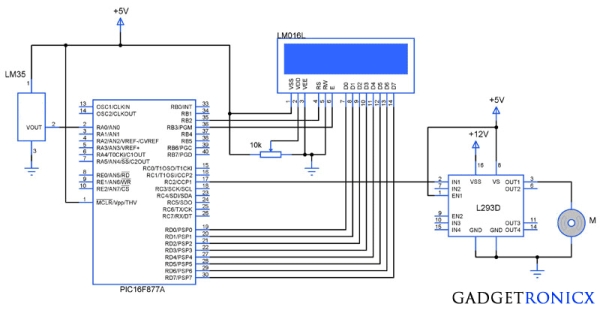
You might have come across several applications where we need to control a specific device based on analog parameter. This Embedded system works in a similar concept where we are about to control the speed of a DC motor using based on the external temperature. The rise in temperature will result in increase in speed of the motor and vice versa. These type of Temperature controlled fan systems can generally be used to maintain temperature of a room or object automatically.
DESIGN OF TEMPERATURE CONTROLLED FAN SYSTEM:
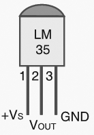
The temperature is measured by means of a temperature sensor LM35.
The output voltage of the sensor is fed to the A/D channel of the Microcontroller.
Based on the sensed temperature the speed of the motor is controlled using PWM .
Several temperature ranges was set in the code to vary the motor speed based on the level of temperature sensed.
The speed of the motor is controlled by using PWM.
Lm 35 is used to sense the external temperature which is capable of sensing temperature ranges from -55 to 150 C. The output voltage is proportional to the temperature hence there is no need of trimmers to calibrate the reading. The output voltage of this sensor varies by 10mv per degree change in temperature.
CALIBRATION:
We are using a 10 bit ADC and Vcc as Vref to the ADC module of the Controller. So in order to determine the step size we have to divide the Vref by our resolution that is 2^10 ( 1024 ).
Step Size = 5 / 1024 = 4.83mV
We obtain a change of 10mV with each rise or fall in temperature from the sensor. And value in the ADC register will alter by two steps with each degree change in the sensor since two increments of step size i.e 4.833mV * 2 = 9.96mV which is approximately equal to 10mV. So in order to obtain the original value we have to divide the contents in the ADC register by 2
CODE:
This code was built using CCS compiler for PIC Microcontrollers.
The above code uses built in functions in the CCS compiler to use the A/D and PWM feature in the Microcontroller. The received analog value is calibrated to display the temperature in the LCD. The “real_value” int value is converted to character using “sprintf” in order to display the temperature values.
The temperature ranges and duty cycle of the PWM is given using the subroutine “.motor”. So the microcontroller runs a check on the temperature every time and alters the speed of the motor based on it.
VEML3235SL is an advanced ambient light sensor with an I2C protocol interface and designed using the CMOS process
VEML3235SL is an advanced ambient light sensor with an I2C protocol interface and designed using the CMOS process. The VEML3235SL incorporates a photodiode, amplifiers, and analog circuits in a single chip. The best spectral sensitivity is used to obtain a response close to the response of a real human eye. It has excellent temperature compensation and a robust refresh rate setting that does not need an external RC low pass filter. Software shutdown mode is provided, which reduces power consumption to be less than 1 μA. The sensor’s operating voltage ranges from 2.6 to 3.6 V and can detect a wide range of ambient light intensities.


 technology, the Vishay Semiconductors VCNL4035X01 combines photo-detectors for proximity and ambient light, a signal conditioning IC, a 16-bit ADC, and a driver for up to three external IREDs in one compact 4 x 2.36 x 0.75 mm surface-mount package. The AEC-Q101 qualified sensor features an interrupt function and supports the I2C bus communication interface for portable electronics and smart home, industrial, and automotive applications.