Quantcast
Channel: temperature | Battery Guide
Viewing all 365 articles
Browse latest View live

Online Monitoring of Temperature of Conductors Using Zigbee and GSM

$
0
0

Project Summary

An on-line monitoring system of temperature of conductors and fittings based on GSM SMS and Zigbee is produced in this project, by which the temperature of conductors and fittings can be monitored in real-time and some accidents caused by the increased temperature can be avoided. The principle and the feature of GSM SMS and Zigbee communication are analyzed. The construction of this system is outlined, and the force modal of calculating the variety of the sag due to the increased temperature of conductors is built. The Zigbee communication module is produced based on RF4CE standard. Finally, the software and hardware design of the online temperature monitoring unit of conductors and fittings are outlined.

Project Description

With fast development of economy in India, the demand of electricity is higher and higher, and the problem between lag of construction of network and inadequacy of transmission capacity becomes increasingly prominent, which exacerbates the unharmonious contradictions of development between power grids and power generation structure. Some provinces and cities have begun to take power limited policies to alleviate contradiction of the current electricity supply-demand, how to resolve this problem has become imperative responsibility for many power workers. Recently, in order to prevent overloading of transmission lines, domestic power system usually adopts the static, conservative transmission capacity value in design, which is a conservative static value based on the severest weather conditions.

Online Monitoring of Temperature of Conductors Using Zigbee and GSMHowever, such severe weather conditions rarely occurred, and it has resulted in the inefficient use of potential transmission capacities in most time. In the situation of “east-west power transmission, south-north power transaction, nationwide electricity interconnection”, long-distance, large-capacity and high-voltage transmission lines will be more and more. By 2010, the transmission capacity of some main lines of 500 kV will reach or exceed 1 GW. By 2020, the transmission capacity for most lines of 500 kV will reach 1 ~ 1. 5GW. Some normal current for heavy short lines will reach 2 GW, which will be near 3 GW in accidents. Now, according to the traditional technology, the transmission capacity can be increased only by adding transmission lines. However, it is becoming more and more difficult to build new transmission lines with the transmission lines increased.

From the perspective of sustainable development and environmental protection, we should pay more attention from power grids expansion to increase the potential transmission capacity of available transmission lines, and enhance the transmission capacity of power grids, so as to resolve the problems between high requirement of electricity and difficulty of new transmission line. In March 2005, the State Grids held a particular meeting about improving the transmission capacity of power grids in Beijing, the meeting pointed out that at the same time of building main electrified wire netting of super high voltage, we need actively and fully tap the potential of existing capacity. At present, some areas adopt the allowable temperature value of 70 to 80 or even 90. Properly increasing the allowable temperature of existing conductors can increase stable carrying capacity of transmission lines, thereby the normal transmission capacity is improved. The method is a breakthrough of current technical regulations, the impact caused by improving conductor temperature on conductors, the mechanical strength and the lifespan of matched fittings, the increase in sag and so on should be studied. In addition, if the conductor temperature and the sag can be real-timely monitored, the dynamic regulation of the transmission capacity, such as day and night, cloudy and sunny, summer and winter under the different environmental conditions can be realized to improve the transmission capacity. In order to meet these demands, an on-line monitoring system of temperature of conductors and fittings based on GSM SMS and Zigbee is studied and developed in this paper.

Introduction to GSM SMS, ZigBee and LM35

A. GSM SMS
GSM (Global System Mobile Communications) is a global digital mobile communication system, whose coverage is the most widely, phone owners is the largest, and reliability is very high. SMS (Short Message Service) is a kind of short message transmitted. In fact, the information transmission is achieved by receiving and sending text message in the businesses center between mobile phones and other short message carriers, and the businesses center is an independent operating system of GSM network whose main function is submitting, storing, and transferring short message. SMS is a special and important service as well as calling for users by GSM system. In this project, a self-designed industrial GSM module is selected to finish the transmission and the decoding of the monitoring data through AT command and coding of short message PDU (Protocol Data Unit).

B. ZigBee
ZigBee wireless network technology is a new standard launched and made by ZigBee Alliance. The alliance, founded in August 2001, is a fast-growing and non-profit organization, and it aims is to provide consumers with more flexible and easier electronic products. The second half of 2002, four large corporations including the British company Invensys, Mitsubishi Electric Corporation, Motorola and the Dutch giant Philips Semiconductor Corporation jointed together to announce that they would join the “ZigBee Alliance” to invent the next-generation wireless communication standards named “ZigBee”, which became a significant milestone in the development process. In October 2004, the ZigBee Alliance announced a version 1.0 of ZigBee protocol, and in December 2005 version 1.1. ZigBee uses free frequency bands of 2.4 GHz and 900 MHz, and its transmission rate is 20 kbps to 250 kbps. In this paper, the perfect chip cc2430 is selected to design the wireless hardware platforms of ZigBee, a standard ZigBee wireless network module is produced, and a reduced version of ZigBee wireless network protocol is programmed. The Zigbee module and protocol have been successfully applied to power system, medical and some other fields.

ZigBee is the set of specs built around the IEEE 802.15.4 wireless protocol. The IEEE is the Institute of Electrical and Electronics Engineers. They are a non-profit organization dedicated to furthering technology involving electronics and electronic devices. The 802 group is the section of the IEEE involved in Information technology—Telecommunications and information exchange between systems—Local and metropolitan area networks including mid-sized networks. Group 15.4 deals specifically with wireless networking (Wireless Medium Access Control (MAC) and Physical Layer (PHY) Specifications for Low-Rate Wireless Personal Area Networks (WPANs) technologies.
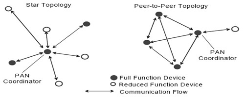
Network Topologies
Depending on the application requirements, an IEEE 802.15.4 LR-WPAN may operate in either of two topologies: the star topology or the peer-to-peer topology. Both are shown in Figure. In the star topology the communication is established between devices and a single central controller, called the PAN coordinator.

Online Monitoring of Temperature of Conductors Using Zigbee and GSM Schematic
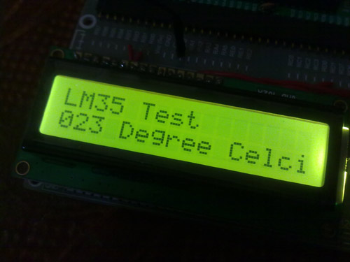
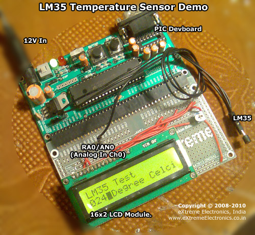
Temperature Measurement
Temperature can be measured via a diverse array of sensors. All of them infer temperature by sensing some change in a physical characteristic. Six types with which the engineer is likely to come into contact are: thermocouples, resistive temperature devices (RTDs and thermostats), infrared radiators, bimetallic devices, liquid expansion devices, and change-of-state devices.

The Overall Structure of Online

Monitoring System
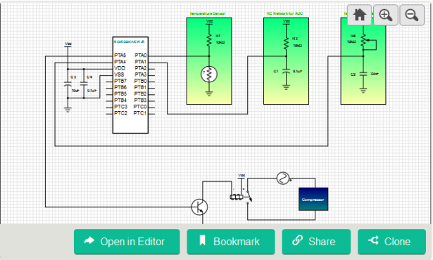
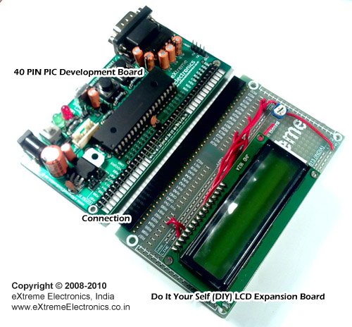
The online monitoring system of temperature of conductors and fittings based on GSM SMS and Zigbee is mainly composed of the municipal monitoring center, the communication unit, the temperature monitoring unit and the expert software, the topology of system is shown in Fig.1. The communication unit is installed on the tower with both GSM and Zigbee communication modules, and the temperature monitoring unit on the corresponding conductors with the same potential.


For more detail: Online Monitoring of Temperature of Conductors Using Zigbee and GSM

The post Online Monitoring of Temperature of Conductors Using Zigbee and GSM appeared first on PIC Microcontroller.


80V BUCK-BOOST CHARGING CONTROLLER WITH MPPT FOR SOLAR PANELS

$
0
0

The LT8491 from Analog Devives includes Maximum Power Point Tracking (MPPT) for solar panels, with algorithms, lead acid and lithium ion batteries up to 80V.

Analog Devices (ADI) has introduced a buck-boost Maximum Power Point Tracking (MPPT) battery charging controller that includes algorithms for charging sealed lead acid, gel and flooded cells, and Li-Ion batteries up to 80V alongside a solar panel.

Features:

  • VIN Range: 6V to 80V
  • VBAT Range: 1.3V to 80V
  • Single Inductor Allows VIN Above, Below, or Equal to VBAT
  • Automatic MPPT for Solar Powered Charging
  • Automatic Temperature Compensation
  • I2C Telemetry and Configuration
  • Internal EEPROM for Configuration Storage
  • Operation from Solar Panel or DC Supply
  • Four Integrated Feedback Loops
  • Synchronizable Fixed Frequency: 100kHz to 400kHz
  • 64-Lead (7mm × 11mm × 0.75mm) QFN Package

The LT8491 includes MPPT, temperature compensation and I2C interface for telemetry and control. It operates from input voltages above, below or equal to the regulated battery float voltage with three selectable Constant Current Constant Voltage (CC-CV) charging profiles, making it suitable for charging a variety of battery chemistry types including sealed lead acid, gel and flooded cells, and Li-Ion. All charge termination algorithms are provided onboard, eliminating the need for software or firmware.

Read more: 80V BUCK-BOOST CHARGING CONTROLLER WITH MPPT FOR SOLAR PANELS

The post 80V BUCK-BOOST CHARGING CONTROLLER WITH MPPT FOR SOLAR PANELS appeared first on PIC Microcontroller.

RA2E1 – 48MHZ ARM® CORTEX®-M23 ENTRY LINE GENERAL PURPOSE MICROCONTROLLER

$
0
0

Renesas Electronics has announced the release of 48 new RA2E1 Group microcontrollers for cost-sensitive and space-constrained applications. Based on the 48-MHz Arm Cortex-M23 core, these new entry-line single-chip devices offer 16-KB SRAM memory, 128-KB code flash, and support a wide operating voltage range of 1.6V to 5.5V and a large selection of packages viz. LQFP, QFN, LGA, BGA, and Wafer Level Chip Scale Package (WLCSP).

The RA2E1 Group of microcontrollers with key features like optimized combinations of superior performance, ultra-low-power consumption, innovative peripherals, and small package options are ideal for cost-sensitive applications and space-constrained applications. Additionally, these MCUs serve as an entry point into our RA2 Series, offering a seamless upgrade to larger RA Family devices with hardware and software scalability. Besides, these devices include an AES cryptography accelerator, a true random number generator (TRNG), and memory protection units that provide the fundamental blocks to develop a secure IoT system.

Key Features Of RA2E1 Microcontrollers

  • 48 MHz Arm Cortex-M23 CPU core
  • Integrated flash memory options from 32KB to 128KB; and 16KB RAM
  • Support for wide operating voltage range: 1.6V – 5.5V
  • Pin counts from 25- to 64-pin
  • Package options including LQFP, QFN, LGA, BGA, and WLCSP (2.14 x 2.27mm)
  • Low power operation: 100µA/MHz in active mode; 250 nA in software standby
  • Integrated next-generation innovative capacitive touch sensing unit with no external components required, lowering BOM costs
  • Enables system costs reduction with on-chip peripheral functions, including a high precision (1.0 percent) internal oscillator, background operation data flash supporting 1 million erase/program cycles, high-current IO ports, and a temperature sensor
  • Pin and peripheral compatibility with RA2L1 Group devices for quick and easy upgrade paths

Read more: RA2E1 – 48MHZ ARM® CORTEX®-M23 ENTRY LINE GENERAL PURPOSE MICROCONTROLLER

The post RA2E1 – 48MHZ ARM® CORTEX®-M23 ENTRY LINE GENERAL PURPOSE MICROCONTROLLER appeared first on PIC Microcontroller.

AXIOMTEK’S INTEL® COFFEE LAKE-BASED MINI-ITX MOTHERBOARD FEATURING THREE DISPLAYS– MANO522

$
0
0

Axiomtek – a world-renowned leader relentlessly devoted in the research, development and manufacture of series of innovative and reliable industrial computer products of high efficiency – is pleased to announce the MANO522, a mini-ITX motherboard powered by the LGA1151 socket 9th/8th generation Intel® Core™ 
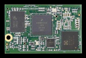
i7/i5/i3 processor (code name: Coffee Lake) with the Intel® H310 chipset. With a small form factor of 17 x 17 cm, this industrial motherboard is an excellent choice for space-constrained environments. Its high computing power, 4K-ready and high expandability make it well-suited for intelligent transportation, factory automation, self-service kiosks, infotainment, and digital signage.

Axiomtek’s MANO522 is a great embedded board for industrial edge computing applications which require high-resolution graphics and reduced energy consumption,” said Michelle Mi, the product manager of the Product Planning Division at Axiomtek. “This industrial motherboard is integrated with Intel® integrated Gfx graphics engine with UHD 4K resolution and provides rapid video acceleration and dual-view capability through the VGA, HDMI and LVDS. To ensure reliable operation, the MANO522 has a wide operating temperature range of 0°C to 60°C. It also supports watchdog timer and hardware monitoring and offers Trusted Platform Module 2.0 (TPM 2.0) for optimum security.

The MANO522 supports two 260-pin DDR4-2666/2400 SO-DIMM sockets for up to 64GB of memory. It comes with rich I/O options, including two Gigabit LANs with Intel® Ethernet controller i211-AT and Intel® Ethernet Connection i219-LM, one HD Codec audio, four USB 3.2 Gen1, two USB 2.0, one RS-232/422/485 with +5/+12V power, five RS-232, one VGA, one HDMI, and one LVDS. The industrial-grade mini-ITX motherboard features two SATA-600 connectors and one M.2 Key M supporting NVMe for additional storage. In addition, it is equipped with one PCIe x16 and one M.2 Key E slot for wireless devices such as Wi-Fi, Bluetooth. The MANO522 is compatible with Windows® 7 and Windows® 10 operating systems.

Read more: AXIOMTEK’S INTEL® COFFEE LAKE-BASED MINI-ITX MOTHERBOARD FEATURING THREE DISPLAYS– MANO522

The post AXIOMTEK’S INTEL® COFFEE LAKE-BASED MINI-ITX MOTHERBOARD FEATURING THREE DISPLAYS– MANO522 appeared first on PIC Microcontroller.

GAN IS AS EASY TO USE AS SILICON: EPC INTRODUCES A 48 V TO 12 V DEMO BOARD

$
0
0

EPC announces the availability of the EPC9157, a 300 W DC-DC demo board in the tiny 1/16th brick size, measuring just 33 mm x 22.9 mm x 9mm (1.3 x 0.9 x 0.35 in). The EPC9157 demo board integrates the Renesas ISL81806 80 V dual synchronous buck controller with the latest-generation EPC2218 eGaN FETs from EPC to achieve greater than 95% efficiency for 48 V input to 12 V regulated output conversion at 25 A. 

Brick DC-DC converters are widely used in data center, computing, telecommunication and automotive applications, converting a nominal 48 V to a nominal 12 V distribution bus, among other output voltages. The main trend has been towards higher power density. eGaN® FETs provide the fast switching, high efficiency and small size that can meet the stringent power density requirements of these leading-edge applications. EPC2218 is the smallest high efficiency 100 V eGAN FET on the market.

Renesas’ ISL81806 is the industry’s first 80V dual-output or two-phase synchronous buck controller with integrated GaN drivers, supporting switching frequencies up to 2 MHz. It uses peak current mode control and generates two independent outputs, or one output with two interleaved phases. It supports current sharing, synchronization for paralleling more controllers and/or more phases, enhanced light load efficiency, and low shutdown current. Protection features include input UVLO, over current, over voltage and over temperature. The ISL81806 can directly drive EPC GaN FETs, ensuring easy design, low component count and low solution cost. The highly integrated ISL81806 reduces BOM cost for GaN solutions because it does not require any microcontroller, current sense amplifiers, or housekeeping power.

Read more: GAN IS AS EASY TO USE AS SILICON: EPC INTRODUCES A 48 V TO 12 V DEMO BOARD

The post GAN IS AS EASY TO USE AS SILICON: EPC INTRODUCES A 48 V TO 12 V DEMO BOARD appeared first on PIC Microcontroller.

Basic Temperature Control for Refrigerators

$
0
0

This design is a basic temperature control for refrigerators that has an electromechanical circuit. It specifically uses MC9RS08KA4CWJR microcontroller which has an 8-bit RS08 central processing unit, 254 bytes RAM, 8Kbytes flash, two 8-bit modulo timers, 2-channel 16-bit Timer/PWM, inter-integrated circuit BUS module, keyboard interrupt, and analog comparator. This project effectively controls temperature of any device using resistors and capacitors.

Basic Temperature Control for Refrigerators

The refrigerator temperature control is a basic RC network connected to an I/O pin. A variable resistor (potentiometer) is used to modify the time the capacitor takes to reach VIH and adjusting its resistance varies that time. A basic voltage divider with one resistor and one thermistor is used to implement the temperature sensor. The thermistor resistance depends on the temperature. For each temperature, we have a different voltage in the divider. This value is effectively measured with the Analog-to-Digital Converter (ADC) implemented by software that uses one resistor, one capacitor, and the analog comparator. In addition, VDD and VSS are the primary power supply pins for the MCU. This voltage source supplies power to all I/O buffer circuitry and to an internal voltage regulator. The internal voltage regulator provides a regulated lower-voltage source to the CPU and other MCU internal circuitry.


For more detail: Basic Temperature Control for Refrigerators

The post Basic Temperature Control for Refrigerators appeared first on PIC Microcontroller.

Voltage, Temperature & Frequency Meter With PIC Micro controller

$
0
0

Features…

  • Voltage, Temperature and Frequency can switching to each others using push buttons.
  • Voltage Meter can measure DC voltage between 0v to 50v.
  • Frequency Meter can measure frequency up to 65KHz.
  • Temperature Meter can use between 00C to 1500C.
  • Every functions can paused using push button.

Voltage, Temperature & Frequency Meter With PIC Micro controller

Instructions…

Voltage meter – 

Volt meter can measure dc voltages up to 50v. 5V is the maximum voltage can handle PIC microcontroller, as it is voltage divider (10K,1.1K) use for convert 50V to 5V . 5v zener diode use for safety of PIC microcontroller analog input pin.

Temperature meter – 

Temperature meter can use between 00C to 1500C. But LM35 sensor can use between -550C to 1500C. Sensor’s resistant is changing opposite to temperature, as it is maximum temperature gives maximum voltage output(5v)  and minimum temperature gives minimum voltage output(0v).  

Frequency meter – 

Theoretically, frequency meter can use up to 65KHz, that is because this circuit made by using Timer 1(16bit) of PIC microcontroller.

Voltage, Temperature & Frequency Meter With PIC Micro controller schematicTimer 0 can only measure up to 256Hz, that is because timer 0 is 8 bit timer. Transistor part is use for safety of microcontroller from amplitude of wave signal. This circuit can apply 12v amplitude or more changing transistor base resistor value(4.7K). I tested it, using 12v amplitude square wave signal

Troubleshooting…

If you have problem about accuracy of voltmeter, temperature meter and frequency meter, you can change values (*1,*2,*3)


For more detail: Voltage, Temperature & Frequency Meter With PIC Micro controller

The post Voltage, Temperature & Frequency Meter With PIC Micro controller appeared first on PIC Microcontroller.

PROVIDING BALANCE WITH THE NX8MM-D168

$
0
0

It may difficult to find a balance when searching for the perfect platform to begin a new project. Trying to balance price, power, and optimal performance while ensuring the end-product accurately represents a company poses a challenge for many out there. To help make this decision easier, we are proud to announce the NX8MM-D168.

Features

  • NXP i.MX8M Mini, Quad-core 1.6GHz ARM Cortex-A53
  • Onboard LPDDR4 1GB/2GB/4GB
  • 3D GPU / 1080p60 VPU
  • GbE / USB / UART / SPI / I²C / PWM / GPIO / MiniPCIe / Audio
  • Support MIPI-DSI / MIPI-CSI
  • 168 pins Configurable I/O Funciton
  • eMMC 4GB~64GB onboard / Micro SD Scoket (Optional)
  • Operation Temperature: -20°C ~ +70°C / -40°C ~ +85°C (Optional)
  • Compact Size Module: 55mm x 35mm
  • OS Support: Yocto Linux, Android 9 Ready
 

The NX8MM-D168 is equipped with the NXP I.MX8M Mini Quad Core Cortex-A53 1.6 GHz ARM CPU with 3D GPU and includes advanced 14LPC FinFET process technology, which provides more speed and improved power efficiency. At slightly less than half the size of a credit card at 35 x 55mm and utilizing a solid 168 pin board-to-board connector with soldered-on LPDDR4 and eMMC, the NX8MM-D168 can be utilized and implemented into many space-limited applications. Despite its tiny size, it incorporates and supports a wide range of Feature-Rich I/O, such as GbE, USB, UART, SPI, I2C, PWM, MIPI-DSI, among other configurations.

Read more: PROVIDING BALANCE WITH THE NX8MM-D168

The post PROVIDING BALANCE WITH THE NX8MM-D168 appeared first on PIC Microcontroller.


Interfacing LM35 Temperature Sensor with PIC Microcontroller.

$
0
0

The are many cool sensors available now a days, ranging from IR distance sensor modules, accelerometers, humidity sensors, temperature sensors and many many more(gas sensors, alcohol sensor, motion sensors, touch screens). Many of these are analog in nature. That means they give a voltage output that varies directly (and linearly) with the sensed quantity. For example in LM35 temperature sensor, the output voltage is 10mV per degree centigrade. That means if output is 300mV then the temperature is 30 degrees. In this tutorial we will learn how to interface LM35 temperature sensor with PIC18F4520 microcontroller and display its output on the LCD module.

First I recommend you to go and read the following tutorial as they are the base of this small project.

After reading the ADC tutorial given above you will note the the PIC MCU’s ADC gives us the value between 0-1023 for input voltage of 0 to 5v provided it is configured exactly as in the above tutorial. So if the reading is 0 then input is 0v, if reading is 1023 then input is 5v. So in general form if the adc read out is val then voltage is.

unsigned int val;
val=ADCRead(0); //Read Channel 0
voltage= ((val)/1023.0)*5;

The above formula give voltage in Volts, to get Voltage in mili Volts (mV) we must multiply it with 1000, so

voltage=((val)/1023.0)*5*1000); //Voltage is in mV

since 10mV = 1 degree, to get temperature we must divide it by 10, so

t=((val)/1023.0)*5*100); //t is in degree centigrade

simplifying further we get

t=((val/1023.0)*500);
t=(val*0.48876);

we round off this value, so

t=round(val*0.48876);

remember round() is a standard c library function

Interfacing LM35 Temperature Sensor with PIC Microcontroller schematicHardware for LM35 based thermometer.

You will need a PIC18F4520 chip running at 20MHz attached with a standard 16×2 LCD Module and LM35 on AN0 pin. LM35 is a 3 pin device as show below.

connect the +Vs Pin to 5v and GND to GND. The output must be connected to the analog input pin 0 of the PIC18F4520 MCU. It is labeled AN0 in the datasheet. It is pin number 2 on the 40 pin package. It is also called RA0 because it is shared with PORTA0.

We will use our 40 PIN PIC Development board to realize the project. The base board has all the basic circuit to run the PIC. The extra part required for this project like LCD and the LM35 temperature sensor are installed in the expansion board.

Interfacing LM35 Temperature Sensor with PIC Microcontroller

The supply for LM35 can be taken from the onboard extra power supply. See the image below.

Just use single PIN female to female wire to connect with the leads of LM35 temperature sensor. Now plug the LCD Expansion board into the expansion slot and burn the hex file to the board using a PIC ISCP Programmer. Your are now all ready to run.

C Source Code For PIC Thermometer Project.


/********************************************************************

LM35 Temperature Sensor INTERFACING TEST PROGRAM

---------------------------------------------------------
Simple Program to connect with LM temperature sensor using the
internal ADC of PIC MCU.

The program displays the current environment temperature on
LCD Module.

MCU: PIC18FXXXX Series from Microchip.
Compiler: HI-TECH C Compiler for PIC18 MCUs (http://www.htsoft.com/)

Copyrights 2008-2010 Avinash Gupta
eXtreme Electronics, India

For More Info visit
http://www.eXtremeElectronics.co.in

Mail: me@avinashgupta.com

********************************************************************/
#include <htc.h>

#include <math.h>

#include "lcd.h"

//Chip Settings
__CONFIG(1,0x0200);
__CONFIG(2,0X1E1F);
__CONFIG(3,0X8100);
__CONFIG(4,0X00C1);
__CONFIG(5,0XC00F);


//Simple Delay Routine
void Wait(unsigned int delay)
{
   for(;delay;delay--)
      __delay_us(100);
}

//Function to Initialise the ADC Module
void ADCInit()
{
   //We use default value for +/- Vref

   //VCFG0=0,VCFG1=0
   //That means +Vref = Vdd (5v) and -Vref=GEN

   //Port Configuration
   //We also use default value here too
   //All ANx channels are Analog

   /*
      ADCON2

      *ADC Result Right Justified.
      *Acquisition Time = 2TAD
      *Conversion Clock = 32 Tosc
   */

   ADCON2=0b10001010;
}

//Function to Read given ADC channel (0-13)
unsigned int ADCRead(unsigned char ch)
{
   if(ch>13) return 0;  //Invalid Channel

   ADCON0=0x00;

   ADCON0=(ch<<2);   //Select ADC Channel

   ADON=1;  //switch on the adc module

   GODONE=1;//Start conversion

   while(GODONE); //wait for the conversion to finish

   ADON=0;  //switch off adc

   return ADRES;
}
void main()
{
   //Let the LCD Module start up
   Wait(100);

   //Initialize the LCD Module
   LCDInit(LS_BLINK);

   //Initialize the ADC Module

   ADCInit();

   //Clear the Module
   LCDClear();

   //Write a string at current cursor pos
   LCDWriteString("LM35 Test");
   LCDWriteStringXY(4,1,"Degree Celcius");

   while(1)
   {
      unsigned int val; //ADC Value

      unsigned int t;      //Temperature


      val=ADCRead(0);   //Read Channel 0

      t=round(val*0.48876);//Convert to Degree Celcius

      LCDWriteIntXY(0,1,t,3);//Prit IT!


      Wait(1000);
   }

}


To compile the above code, lcd.c file must be added to the poject. While the lcd.hmyutils.h must be present in the same project folder. More instruction is available in following articles.

Testing The LM35 Based Thermometer.

Turn on the power supply, the screen should show the current temperature readings. Bring a Hot soldering iron tip near the LM35’s pins, don’t touch it keep it 1 or 2mm away. The screen should update with the rising temperature. Now finally touch the pins of LM35 with the tip of iron, the temperature should rise quickly. Keep it there until temperature rise to 80 degrees, then remove the iron. You can now blow some air by your mouth on the sensor to cool it down.

Fig.: LM35 Temperature Sensor Demo.

Fig.: LM35 Temperature Sensor Demo Hardware Setup.

PIC18F4520 based Thermometer using LM35 Schematic

General Notes

  • For proper working use the components of exact values as shown above.
  • Wherever possible use new components.
  • Solder everything in a clean way. Major problems arises due to improper soldering,solder jumps and loose joints.
  • Use the exact value crystal shown in schematic.
  • Only burning the HEX file to the MCU is NOT enough. PIC18 devices are fairly complex MCU and can be configured in various ways. Chip is configured using the CONFIG Bytes. Although all hex file given in our site comes with embedded CONFIG bytes. But the user must ensure they are programmed to the chip. Any good programmer has the capability to read the configuration information from the hex file and transfer it to the MCU. Programs will not run without proper configuration byte programming. One major job of configuration is to setup proper oscillator and PLL modes without which the MCU won’t execute a single instruction.
  • To compile the above code you need the HI-TECH C and MPLAB IDE. They must be properly set up and a project with correct settings must be created in order to compile the code. So I request you to read the following articles to become familiar with the built steps.
  • To understand the code you must have good knowledge of core C language. Please don’t be confused with the basic concept of the language.
  • You must be familier with project concept and multi source file concept that used used in most professional languages like C.
  • You need Proteus VSM if you want to develop or debug the project without any hardware setup.

Video

Source : Interfacing LM35 Temperature Sensor with PIC Microcontroller.

The post Interfacing LM35 Temperature Sensor with PIC Microcontroller. appeared first on PIC Microcontroller.

Temperature Indicator using PIC microcontroller

$
0
0

Hi friends, today we will see how to make temperature indicator using PIC microcontroller. The basic aim of this project is make you familiar with PIC microcontroller. It also explains how LM35 and 7 segment displays can be interfaced with PIC microcontroller.

Components required:

Following is a list of components required for temperature indicator using PIC microcontroller – mini project:
Temperature Indicator using PIC microcontroller

  • PIC microcontroller (PIC16F676)
  • 4 digit (or 3digit) seven segment display (Common cathode)
  • Temperature sensor (LM35) IC
  • 5V DC power supply

Circuit diagram:

Following figure shows circuit diagram of temperature indicator using PIC microcontroller.

Theory:

In this mini project we have used PIC microcontroller and a four digit seven segment display is interfaced with it. For sensing the surrounding temperature we have used a temperature sensing IC i.e. LM35. You can use a voltmeter to crosscheck whether the indictor giving correct output or not. The output of the temperature in terms of volts will be in the range of mV.

Temperature Indicator using PIC microcontroller SchematicWorking of LM35:

LM35 is an integrated temperature sensor. It produces output voltage proportional to the temperature. The advantage of using LM35 is that it does not require any external calibration technique and it has accuracy of ±0.4 degree Celsius at room temperature. It draws only 60µA from supply and possesses low self heating. Thus the chances of error get minimized.


For more detail: Temperature Indicator using PIC microcontroller

The post Temperature Indicator using PIC microcontroller appeared first on PIC Microcontroller.

Interfacing Temperature Sensor with Microchip PIC16F876A

$
0
0

The tutorial aims at providing the necessary information for interfacing an analog type temperature sensor with a Microchip PIC Microcontroller. PIC (Peripheral Interface Controllers) was introduced in 1985. The PIC16F876A has 8K of Flash Program Memory, 368 bytes of Data Memory (RAM) and many other attractive features. Some features are ADC, USART, and 14 Interrupts all in 28 PDIP Package.

mperature Sensor with Microchip PIC16F876AThe Analog temperature sensor used is LM35. It has a transfer function of 10mv/’c. The output of LM35 is analog voltage which varies with changes in temperature. This analog voltage is digitized using the On-Chip 10bit A/D Converter and the value is displayed on a 2×16 LCD.

It is possible to switch On/Off an external application based on temperature value.

The LCD is based on HD44780 controller. The programming has been done using the MikroC compiler from Mikroelektronika (www.mikroe.com). The demo version has a 2KB Hex Output limit, fortunately it is more than enough for our requirement.

Program

int t1,temp;

char *text[6];

void main()

{adcon1=14;

lcd_init(&portb);

lcd_out(1,1,”Temperature”);

lcd_out(2,8,”‘C”);

while(1)

{t1=adc_read(0);

//temp=0.245*t1;          // For TMP37 Sensor 20mv/’c

temp=0.245*t1*2;        // For Lm35 Sensor 10mv/’c

inttostr(temp,text);

lcd_cmd(lcd_cursor_off);

lcd_out(2,1,text);

delay_ms(100);}}

Interfacing Temperature Sensor with Microchip PIC16F876A SchematicThe program is self explanatory, however let me explain you the calculation done. In a while loop. The Input channel 0 is read and the digitized value is obtained. Now the smallest digitized value is equal to Vref/((2^10)-1). Internal Vref is 4096mV but we will consider 5000mV for the ease of calculation. Multiplying the value obtained above with the digitized value will give us the analog voltage. Since the transfer function of Lm35 is 10mV/’c, we can obtain the temperature.


For more detail: Interfacing Temperature Sensor with Microchip PIC16F876A

The post Interfacing Temperature Sensor with Microchip PIC16F876A appeared first on PIC Microcontroller.

NEW ITX-M-CC452-T10 BOARD WITH BUILT-IN STORAGE SPANS MICROSD, SATA AND MSATA

$
0
0

WINSYSTEMS Debuts Industrial-Rated Mini-ITX Form Factor Carrier for COM Express Type 10 Mini Modules

U.S.-made ITX-M-CC452-T10 board provides extensive connectivity for Type 10 mini-module designs and a production-ready -40C° to +85°C edge computing solution with COMeT10-3900 cards

Grand Prairie, Texas, March 2, 2021 /PRNewswire/ — Leading industrial embedded computing designer and manufacturer WINSYSTEMS today introduced its first Mini-ITX form factor carrier board to complement and support its COMeT10-3900 COM Express Type 10 mini modules. The ITX-M-CC452-T10 carrier platform is designed with industrial components for testing products in development and to deliver highly reliable performance in operating environments with temperatures of -40°C to +85C°.

Our new industrial COM Express carrier provides a reference point for customers when testing and troubleshooting their own or another COM Express Type 10 carrier design,” said WINSYSTEMS’ Technical Sales Director George T. Hilliard. “And, because it supports all interfaces from our recently introduced COMeT10-3900 COM Express modules, these two products can be readily deployed as a complete embedded edge computing platform.

WINSYSTEMS’s newest COM Express market entry offers the assurance of a USA-designed and manufactured product fully backed by expert technical guidance, BIOS customization, and convenient customer service based in the heart of Texas. This translates to superior quality and better support for greater confidence in the end product – coupled with rapid, more predictable delivery for shorter lead times and reduced time to market.

Read more: NEW ITX-M-CC452-T10 BOARD WITH BUILT-IN STORAGE SPANS MICROSD, SATA AND MSATA

The post NEW ITX-M-CC452-T10 BOARD WITH BUILT-IN STORAGE SPANS MICROSD, SATA AND MSATA appeared first on PIC Microcontroller.

ECS RELEASES BRAND NEW INDUSTRIAL-GRADE MINI PC – LIVA M300-W

$
0
0

Elitegroup Computer Systems (ECS), the global leading motherboard, Mini-PC, Notebooks, mobile device and smart city solutions provider, is proud to present the latest light and thin mini PC – LIVA M300-W . LIVA M300-W is designed by iron grey metal chassis with compact size measuring only 12.8 x 12.8 x 2.6 cm. LIVA M300-W is powered by …

ECS RELEASES BRAND NEW INDUSTRIAL-GRADE MINI PC – LIVA M300-W Continue Reading

The post ECS RELEASES BRAND NEW INDUSTRIAL-GRADE MINI PC – LIVA M300-W appeared first on PIC Microcontroller.

Digital Temperature Sensor Circuit

EA W128064-XALG COMPACT LOW-POWER OLED DISPLAY

$
0
0

Display Visions’ 0.84″ 96 x 16 OLED display is ideal for small, compact low-power applications Display Visions’ yellow OLEDs come packaged as a complete module that includes all required logic at only a 1.34 mm thickness. With a built-in controller, 2000:1 contrast ratio, 10 µs response time, viewing angles greater than 160°, and the ability to withstand …

EA W128064-XALG COMPACT LOW-POWER OLED DISPLAY Continue Reading

The post EA W128064-XALG COMPACT LOW-POWER OLED DISPLAY appeared first on PIC Microcontroller.


SCIOSENSE’S ENS210 RELATIVE HUMIDITY AND TEMPERATURE SENSOR WITH I²C INTERFACE

$
0
0

ScioSense’s ENS210 is a high-performance digital output sensor that monolithically integrates one relative humidity sensor and one high-accuracy temperature sensor. The device is encapsulated in a QFN4 package and includes an I²C slave interface for communication with a master processor. Features Compact size: 2.0 mm x 2.0 mm x 0.75 mm Typ. accuracy: temperature sensor ±0.15°C, relative humidity sensor …

SCIOSENSE’S ENS210 RELATIVE HUMIDITY AND TEMPERATURE SENSOR WITH I²C INTERFACE Continue Reading

The post SCIOSENSE’S ENS210 RELATIVE HUMIDITY AND TEMPERATURE SENSOR WITH I²C INTERFACE appeared first on PIC Microcontroller.

COMPACT 3.5 INCH IBASE IB386 SBC FEATURING INTEL ELKHART LAKE SOC

$
0
0

In December 2020, we saw iBase unveiled the release of the 10th generation intel core Mini ITX motherboard. Now, the company has announced its compact 3.5-inch iBase IB386 SBC featuring Elkhart Lake SoC. There was another 3.5-inch ECM-EHL SBC which had a similar Elkhart Lake SoC but, it comes with 1GbE ports instead of the GbE and 2.5GbE ports on …

COMPACT 3.5 INCH IBASE IB386 SBC FEATURING INTEL ELKHART LAKE SOC Continue Reading

The post COMPACT 3.5 INCH IBASE IB386 SBC FEATURING INTEL ELKHART LAKE SOC appeared first on PIC Microcontroller.

MURATA’S SILICON CAPACITORS

$
0
0

Murata BBEC Silicon Capacitor Murata BBEC Silicon Capacitor offers ultra-broadband performance up to 40GHz in a 0201M package with a 0.60mm x 0.30mm (L x W) footprint. This capacitor is resonance-free, allowing ultra group delay variation. It provides high reliability and high stability of capacitance value over temperature, voltage, and aging. Other features include ultra-low insertion loss as well as low ESL …

MURATA’S SILICON CAPACITORS Continue Reading

The post MURATA’S SILICON CAPACITORS appeared first on PIC Microcontroller.

WÜRTH ELEKTRONIK INTRODUCES ITS WSEN-HIDS HUMIDITY SENSOR

$
0
0

Würth Elektronik has developed a micro-electro-mechanical system (MEMS) sensor only 2 × 2 × 0.9 mm in size. Thanks to its low energy requirement and its calibrated and temperature-compensated digital output, the sensor measures humidity and temperature with long-term stability. The WSEN-HIDS humidity sensor is based on advanced MEMS technology: A dielectric polymer absorbs or releases water molecules in …

WÜRTH ELEKTRONIK INTRODUCES ITS WSEN-HIDS HUMIDITY SENSOR Continue Reading

The post WÜRTH ELEKTRONIK INTRODUCES ITS WSEN-HIDS HUMIDITY SENSOR appeared first on PIC Microcontroller.

WORLD’S FIRST! A COMPUTER WITH AUTO HEAT-UP? DFI 3.5” DESKTOP CS551 CAN RUN EVEN AT SUBZERO TEMPERATURES

$
0
0

As edge computing has been rapidly expanding to every corner, users pursue computers to drive more functions with better performance to enhance artificial intelligence analysis capabilities, which brings three new criteria in hardware selection for edge applications: processing power, size, and adaptability to extreme weather. DFI, one of the world-leading industrial PC providers, newly released …

WORLD’S FIRST! A COMPUTER WITH AUTO HEAT-UP? DFI 3.5” DESKTOP CS551 CAN RUN EVEN AT SUBZERO TEMPERATURES Continue Reading

The post WORLD’S FIRST! A COMPUTER WITH AUTO HEAT-UP? DFI 3.5” DESKTOP CS551 CAN RUN EVEN AT SUBZERO TEMPERATURES appeared first on PIC Microcontroller.

Viewing all 365 articles
Browse latest View live


<script src="https://jsc.adskeeper.com/r/s/rssing.com.1596347.js" async> </script>