The Incubator Temperature Regulator is made on a breadboard to demonstrate how to program and set the temperature of the regulator. It uses an LM35 temperature sensor, a serial LCD made with a PIC16F628A microcontroller and an Arduino Nano. The low & high setpoint is configurable to maintain the temperature range. An LED is used to represent the function of the heater. When the temperature is below the low setpoint, the LED comes “ON”. It goes “OFF’ when the temperature rises above the high setpoint.
Supplies
1. One Arduino Nano with USB Cable
2. One PIC16F628A
3. LM35 Temperature Sensor
4. One Liquid Crystal Display (LCD)
5. Four 10 Kilo-Ohms Resistors
6. One 330 Ohms Resistor
7. One 10 Kilo-Ohms Reisitor
8. Three Push-button Switches
9. One Big Breadboard
10. Three Mini-Breadboard
Step 1: Build a Serial LCD With PIC16F628A Microcontroller and Connect to the Arduino Nano
A serial LCD by Jason Jacob on LDmicro Github page (https://github.com/LDmicro/LDmicro/wiki/Stopwatch3-over-serial-LCD-based-on-HD44780-controller) was built on a breadboard. The MAX232 circuit, the transistor, and the push-button switches were removed from Jason’s serial LCD to give the stripped-down version above. Download and unzip the files. Upload the .hex file into the PIC16F628A microcontroller with the PICkit-3 programmer as demonstrated in tutorial 5. Pin 7 of the PIC16F628A should be connected to pin TX of the Arduino Nano circuit. The three push-button switches are used to adjust the low and high setpoints of the controller.
Step 2: Program the Arduino Nano With a LDmicro
See link to the LDmicro program. The code is compiled for Arduino Sketch in LDmicro. Then the Arduino IDE is used to upload the sketch to the nano.
Observe that the displayed home page shows the temperature reading in both Celsius and Fahrenheit. Pressing the menu button once displays the low setpoint menu for the adjustment of the low setpoint. A second press of the Menu button displays the high setpoint menu for its adjustment. When the temperature goes below the low setpoint, the LED which represents the heater comes ON. It goes OFF when the temperature is higher than the high setpoint.
Axiomtek – a world-renowned leader relentlessly devoted in the research, development and manufacture of series of innovative and reliable industrial computer products of high efficiency – is pleased to announce the PICO317, its new fanless Pico-ITX SBC powered by the onboard quad-core Intel® Atom® x5-E3940 processor (code name: Apollo Lake). This tiny 2.5-inch embedded board can withstand a wide operating temperature range of -40°C to +70°C (-40°F to +158°F) for use in harsh and space-constraint environments. It comes with dual-display capability through 4K-ready HDMI and 18/24-bit single/dual channel LVDS. Combined with a rugged design and high-speed processing, the PICO317 is suitable for a variety of industrial IoT applications, including industrial automation, transportation, retail and more.
Responding to the surging demand for imaging processing, the powerful PICO317 has Intel® integrated Gfx graphic engine which optimizes the graphics performance and brings captivating visual experiences. This low-power industrial motherboard has a full-size PCI Express Mini Card slot supporting mSATA for wireless and storage. It has three USB 3.0 ports to connect with industrial cameras for machine vision applications.
The PICO317 is a feature-rich, flexible and customizable pico-ITX form factor motherboard that is a great choice for many IIoT applications. Its fanless and ultra-compact design allows easy installation in environments and more flexible product designs. The varieties of I/O connectors are offered to deliver true customer value for fewer integration hassles,
said Kevin Lin, a product manager of the Motherboard Division at Axiomtek.
The feature-rich PICO317 supports one DDR3L-1867 SO-DIMM slot with up to 8 GB of system memory. It is equipped with one Gigabit Ethernet port with Intel® i211AT which supports Wake-on-LAN and PXE Boot ROM. Other I/O interfaces include two RS-232 ports, two USB 2.0 ports, three USB 3.0 ports, one HD Codec audio and one SATA-600 slot. This stunning Pico-ITX board also has SMBus that is compatible with I2C for smart battery support. To meet the industrial needs, it has a 5VDC input with AT auto power-on function. Moreover, the PICO317 has a watchdog timer and offers hardware monitoring functions to detect CPU/system temperature and voltage to ensure reliable operation.
Advantech, a leading global provider of IoT systems and embedded platforms, is pleased to announce the latest 3.5″ SBC MIO-5393 powered by 9th Gen. Intel® Xeon®/Core. Featuring a compact 146 x 102 mm (5.78 x 4.01 in) design, this single board computer offers impressive I/O functionality and domain-focused features like CANBus. Advantech’s embedded small form-factor SBC’s are designed to support wide operating temperature ranges (-40 ~ 85°C / -40 ~ 185°F) and harsh environments, making it an excellent choice for applications that require high processing speeds, such as Automated optical inspection machines, passenger information systems, outdoor kiosks, surveillance and medical devices.
High-performance Computing and Rapid NVMe Storage
Advantech’s platform is the first 3.5″ SBC to feature the latest 9th Gen. Intel® Xeon®/Core with six core computing power. This new generation SBC doubles USB speed by utilizing USB 3.2 Gen 2 (10Gbps). Using a built-in Gen9LP graphics engine, MIO-5393 supports three simultaneous displays with 48bit LVDS (eDP optional), HDMI (up to 4k@30Hz), and DisplayPort (up to 4k@60Hz). MIO-5393 supports up to 32GB(64GB*) memory size dual-channel DDR4 2400MHz and features a M.2 M-Key 2280 slot for NVMe/PCIE Gen3x4 high-speed PCIe SSD storage, providing high data rates for computing and storage. This makes the MIO-5393 an excellent solution for performance demanding applications that require computing power in a compact 3.5″ form-factor.
Advantech’s MIO-5393 features the innovative Quadro Flow Cooling System (QFCS) thermal solution for excellent temperature management. This advanced high-efficiency low profile cooling solution facilitates extreme computing performance. This thin and light thermal solution features a silent fan, enabling heavy CPU loading without CPU speed throttling. MIO-5393 utilizes two different TDP (25W/45W) SKUs with either active or passive heatsink to support extended temperature operation (-40 ~ 85°C / -40 ~ 185°F). Advantech’s advanced thermal-solution leverages four symmetrical screw holes around the CPU to drastically reduce the thermal resistance and to dissipate the heat quickly. Advantech’s 3.5″ SBC effectively solves the temperature and thermal issues confronting outdoor kiosks, railway applications and factory environments.
Axiomtek – a world-renowned leader relentlessly devoted in the research, development and manufacture of series of innovative and reliable industrial computer products of high efficiency – is proud to introduce the UST200-83H-FL, a palm-sized in-vehicle IoT gateway powered by the low-power consumption Intel® Atom x5-E3930 processor (codename: Apollo Lake-I). It is certified with CE and FCC and is in compliance with ISO 7637-2. With the function of the Smart Ignition power control, the rugged embedded system can arrange a power on/off schedule to protect the vehicle battery from unstable voltage. This high-performance IoT gateway delivers an excellent price-performance ratio for in-vehicle applications.
The Axiomtek UST200-83H-FL offers a power-efficient design to maximize operational efficiency. This well-developed in-vehicle box PC is equipped with Smart Ignition power control to meet various in-vehicle application needs. By switching the power mode, it supports 12 and 24 VDC typical automotive power input or wide-range 9 to 36V DC power input. The flexible IoT gateway is designed for all kinds of in-vehicle applications from the shuttle bus, police car, ambulance, cold chain truck, and forklift to heavy-duty vehicles,” said Eason Yang, a product manager of Product PM Division at Axiomtek. “Thanks to its ruggedized design for harsh environments, the UST200-83H-FL is able to operate under a wide temperature range from -40°C to +70°C and vibration of up to 3 Grms. This IoT gateway supports both wall mounting and DIN-rail mounting. Its ultra-lightweight and compact design is ideal for space constraint environments.
The fanless UST200-83H-FL comes with one DDR3L-1866 SO-DIMM slot with up to 8GB of system memory. It has one full-size PCI Express Mini Card slot (USB/PCIe interface with SIM socket) and one half-size PCI Express Mini Card slot (mSATA/USB/PCIe interface) for a wide selection of modules. It has a half-size mSATA shared with its PCI Express Mini Card slot for storage. Its I/O options include one DB9 RS-232/422/485 or CANBus 2.0 A/B supporting SocketCAN, one VGA port, two USB 2.0 ports, two RJ-45 LAN ports with isolation and one DB9 8-bit programmable DIO. This cost-efficient in-vehicle PC is compatible with Windows®10 IoT and Linux. Besides, it supports Axiomtek’s exclusive AXView software to fulfill the requirement of remote monitoring.
The echolocating bat is a wonderful animal that is unique in so many different ways: it is the only truly flying mammal, it can use air-coupled sonar to navigate in complete darkness while flying, it can allow its body temperature to drop to as low as 1degC (torpor) to save energy, and it has adapted to a huge range of climates and food sources (e.g., fruits, crawling and flying insects, nectar, fish, blood, etc). That’s nice, but why would a neuroscientist or engineer specifically study bats?
From a computational neuroscience perspective, bats are remarkable because of the very short timescale on which they operate. The barrage of returning sonar echoes from a bat’s near-environment lasts approximately 30 milliseconds following a sonar emission with the echo from a specific target lasting, at most, a few milliseconds. At this timescale, a particular neuron has the opportunity to fire only one or two spikes to represent the echo. Unlike the “traditional” view of cortical processing where many spikes are integrated over time to compute an average rate, the bat must rely on populations of neurons that respond transiently but selectively to different objects in the environment. In these neural circuits, the details of spike timing, synaptic dynamics, and neuron biophysics become extremely important. Flying at speeds anywhere from 1m/s to 6 m/s, a bat’s sensory world jumps from pulse to pulse as it flies through the world. Sensory prediction is therefore likely to be very important in this animal. In spite of all this behavioral specialization, the bat brain is organized like most other mammalian brains suggesting that echolocation arises from only small modifications of the typical mammalian auditory system. From an engineering standpoint, biosonar systems (e.g. bats and dolphins) have inspired the design of very sophisticated sonar and radar systems that can map distant surfaces and track targets with great precision. Even with powerful mathematical tools and decades of experience, however, our best systems still do not rival the perceptual capabilities of dolphins. Many bats demonstrate incredible aerial agility, flying in complete darkness through branches and caves while hunting evasive insects. These animals perform such tasks in real-time with a total power consumption (including flight) measured in Watts, not hundreds of Watts. In addition to the ability to navigate in complete darkness by echolocation, both bats and dolphins live in very social environments using echolocation in group situations without any obvious problems with interference. All of these capabilities are highly desired by current military programs developing unmanned-aerial vehicles (UAV) especially since many of the target environments are in places where Global Positioning System (GPS) signals are unavailable and obstacle locations are not mapped.
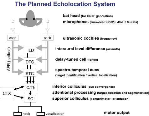
Goal: Our goal is to construct a flying bat-sized creature that uses ultrasonic echolocation to both navigate and scrutinize its environment sufficiently to distinguish between obstacles and “insects”. The bat’s sensory and motor system will be constructed from neural models and implemented using “neuromorphic” VLSI techniques. Our intention is two-fold: 1) to test these neural algorithms in a real-time, closed-loop behavioral situation, and 2) to develop useful sonar sensors for use in miniature aircraft systems.
The Bat Head
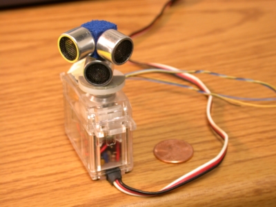
We are working with two different hardware systems: a physically-larger single-frequency sonar system (“narrowband”) and a tiny broadband system. The narrowband system is being used to rapidly test concepts following initial software tests. Photos of these two systems are found below:
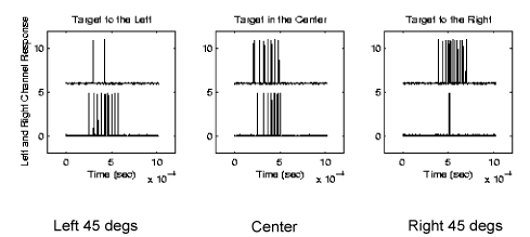
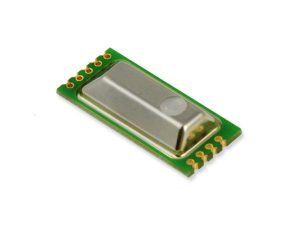
In the photo to the left, is our narrowband sonar system that operates only on a frequency of 40 kHz. The fixed arrangement of the microphones was chosen to produce a difference in echo amplitude with azimuthal direction. The current system roughly extracts direction and range and is capable of servoing the head (which is mounted on an model airplane servo) to track moving targets in real-time.
On the right, we have a photo of our broadband system using a baked polymer clay bat head with a tiny Knowles (FG3329) microphone soldered to the end of a group of wires. This system has two broadband ultrasonic (and audio) microphones that will feed our silicon cochleae chips.
Both of these physical heads produce intensity difference cues at each microphone that allows the system to determine the angle of the arriving echo.
An Ultrasonic Cochlea
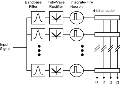
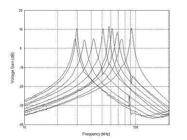
Echolocating bats specialize in high-frequency hearing using echolocation sounds that typically range in frequency from 20 kHz to 100 kHz. While some bats are specialized for specific frequencies with cochlear filtering at extremely high Q10dB values, we are studying bats that use a broadband vocalization and are ultrasonic frequency generalists (e.g., Myotis lucifugus) with Q10dB values in the range of 10 to 30. Good frequency resolution is important for vertical localization, discriminating close objects, as well as for prey discrimination.
To support our ongoing work in modeling bat echolocation, a binaural, ultrasonic cochlea-like filter bank has been designed with moderate quality (Q) factor (as high as 65) with spiking neurons that are driven by the filter outputs. The neuron addresses are reported off chip at the time of the spike in an unarbitrated fashion and in current-mode to reduce the amount of capacitively-coupled feedback into the filters. This chip was fabricated in a commercially-available 0.5 um CMOS process and consumes 0.425 milliwatts at 5 volts.
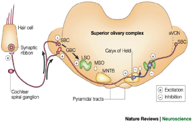
Modeling the lateral superior olive (LSO), dorsal nucleus of the lateral lemniscus (DNLL), and the inferior colliculus (IC)
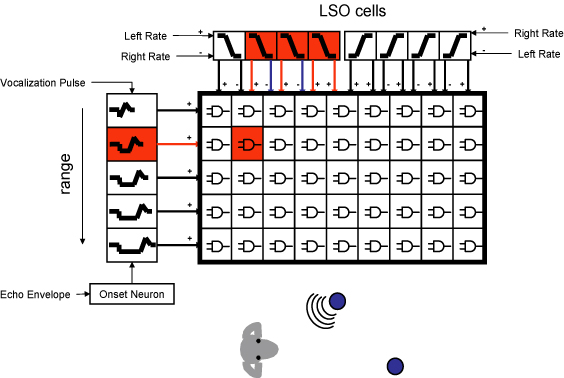
When echoes arrive from different directions, the number of spikes generated in the auditory nerve and the cochlear nucleus varies with the intensity at each ear. Using this information, the first binaural nucleus in the mammalian auditory system, the lateral superior olive (or LSO) becomes selective to the direction of arrival. These cells are excited by the intensity from one ear and inhibited by the intensity from the other ear.
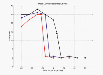
The binaural LSO response and the monaural response from the cochlear nucleus is projected to the inferior colliculus (IC) via the doral nucleus of the lateral lemniscus (or DNLL), resulting in very similar responses in both DNLL and IC. With similar responses in the LSO as in the IC, one can ask the question, “what kind of computation is going on here?” In the figure to the left is a set of tuning curves for three LSO cells that have different synaptic weightings from the left and right ears. By comparing the responses of the population of LSO cells, each of which have different synaptic weightings, we can determine which direction an echo is arriving from.
In this work, we are working with a single frequency system (40kHz) and brief burst of ultrasonic energy. Here we have designed a VLSI circuit that mimics the spiking neurons of the LSO, DNLL, and IC to create the responses seen in the bat brainstem neurons.Our experimentation with the circuits and model seem to suggest that the extra synaptic interaction at the level of the DNLL and the IC creates an temporal interaction between individual echoes resulting from a single vocalization and even interactions between echoes from previous vocalizations.
We have built a multi-layer neuron chip that can simulate the LSO, DNLL, and the IC using spiking neurons. With this chip, we are exploring the role of long-lasting inhibition and refractory periods on how the spatial receptive fields of bat brainstem neurons change when multiple echoes are presented to the animal. This is a largely unexplored area of research and where there have been experiments, they show results that suggest that bats may need a more sophisticated signal processing system to untangle all of the interactions.
Delay-tuned Cells (Range tuning)
Information about target range has many uses for bats during both prey-capture and navigation tasks. Beyond the extraction of distance and velocity, it may be important for less obvious tasks, such as optimizing the parameters of the echolocation process. For example, as a bat approaches a target, it alters the repetition rate, duration, spectral content, and amplitude of its vocalizations. Not only is echolocation used for insect capture, it provides to the bat information about obstacles, roosts, altitude, and other flying creatures.
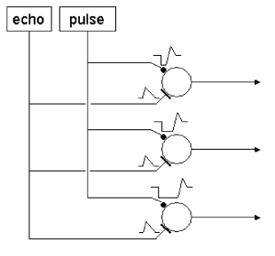
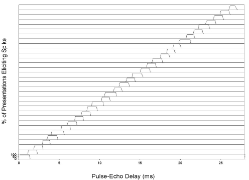
In the bat’s brainstem and midbrain exist neural circuits that are sensitive to the specific difference in time between the outgoing sonar vocalization and the returning echo. While some of the details of the neural mechanisms are known to be species-specific, a basic model of re-afference-triggered, post-inhibitory rebound timing is reasonably well supported by available data. Neurons have been found in bats that show a ‘facilitated’ response to paired sounds (a simulated vocalization and an echo) presented at particular delays. The cells’ responses to sounds presented at the appropriate delays are much greater than the sum of the responses to the individual sounds presented alone. These cells are part of a larger class of neurons called ‘combination-sensitive’ neurons, and are specifically referred to as delay-tuned cells. Delay-tuned cells are found at manylevels in the bat auditory system. They have been found in the inferior colliculus (IC), the medial geniculate body (MGB), and the auditory cortex. Disruption of cortical delay-tuned cells has been shown to impair a bat’s ability to discriminate artificial pulse-echo pair delays. It is likely that delay-tuned neurons play a role in forming the bat’s perception of range, although delay-tuned cells have also been shown to respond to the social calls of other bats.
We have designed low-power, analog VLSI circuits to mimic this mechanism and have demonstrated range-dependent outputs for use in a real-time sonar system. These circuits are being used to implement range-dependent: vocalization amplitude, vocalization rate, and closest target isolation. Power consumption is approximately 2-4 mW.
A Convergence of Range and Azimuth ( 2-D cells )
In our latest project, we have combined the work on LSO modeling which extracts information about azimuth and combined it with the range tuning cells above to create “2-D cells” which respond to a combination of range and azimuth. These circuits are coincidence detectors that respond to echoes originating from a particular direction and range.
Texas Instruments’ buffer features stuck bus recovery
Texas Instruments’ TCA4307 is a hot-swappable I2C bus buffer that supports I/O card insertion into a live backplane without corruption of the data and clock lines. Control circuitry prevents the backplane-side I2C lines (in) from being connected to the card-side I2C lines (out) until a stop command or bus idle condition occurs on the backplane without bus contention on the card. When the connection is made, this device provides bidirectional buffering, keeping the backplane and card capacitances isolated. During insertion, the SDA and SCL lines are pre-charged to 1 V to minimize the current required to charge the parasitic capacitance of the device.
The TCA4307 has stuck bus recovery, which automatically disconnects the bus if it detects either SDAOUT or SCLOUT are low for about 40 ms. Once the bus is disconnected, the device automatically generates up to 16 pulses on SCLOUT to attempt to reset the device which is holding the bus low. When the I2C bus is idle, the TCA4307 can be put into shutdown mode by setting the EN-pin low, reducing power consumption. When EN is pulled high, the TCA4307 resumes normal operation. This buffer includes an open-drain READY output pin, which indicates that the backplane and card sides are connected. When READY is high, the SDAIN and SCLIN are connected to SDAOUT and SCLOUT. When the two sides are disconnected, READY is low.
Supports bidirectional data transfer of I2C bus signals
Operating power supply voltage range: 2.3 V to 5.5 V
Ambient air temperature range (TA): -40°C to +125°C
Stuck bus recovery featuring automatic bus recovery
1 V pre-charge on all SDA and SCL lines prevents corruption during live insertion
Accommodates standard-mode and fast-mode I2C devices
Supports clock stretching, arbitration, and synchronization
The EE895 sensor module is ideal for use in climate measuring devices. Pressure and temperature compensation ensure a high CO2 measuring accuracy.
The new EE895 sensor module from E+E Elektronik measures CO2, temperature and ambient pressure. The small 3-in-1 module is an ideal choice for measuring instruments used for ventilation and climate control, in building automation or for process control. Due to its low power consumption, the module is also suitable for battery-operated devices such as hand-held meters, data loggers or wireless transmitters. The temperature and pressure compensation ensures high CO2 measurement accuracy under changing environmental conditions.
A Single Module – 3 Measurands
Additionally to CO2 concentration up to 10 000 ppm the EE895 module measures also the temperature and ambient pressure. The pressure and temperature compensation with on-board sensors minimizes the environmental influences onto the CO2 measurement. Thus the module offers a constantly high CO2 measurement accuracy, independent of altitude or changing ambient conditions.
Long-Term Stable CO2 Measurement Principle
The dual wavelength NDIR CO2 measuring principle with auto-calibration ensures long-term stable measurements, as it automatically compensates for aging effects and is particularly resistant to contamination. The factory multi-point CO2 and temperature adjustment procedure leads to an excellent CO2 measurement accuracy over the entire temperature working range of -40…60 °C (-40…140 °F).
Easy Design-In
The measured data for CO2, temperature and pressure is available on the I2C or UART interface. The very small dimensions of only 35 mm x 15 mm x 7 mm (1.38″ x 0.6″ x 0.27″) and various mounting options facilitate the design-in of the sensor module.
Flexibly Configurable
The EE895 module can be flexibly configured via the digital interface. The CO2 measurement interval can be set according to the application and the power requirements.
The Over-current limit load switch project presented here provides full protection to devices and loads from access load conditions. The default current limit is set to 1 Amp, however, this load limit is adjustable from 0.4A to 2A with the help of R4 ISET resistor. When an overload condition occurs circuit responds to that overload condition that lasts longer than a fixed blanking period by turning off the load, followed by a retry after the auto-restart time, auto-retry time is 127.5ms. Flag output is pulled up with R1 and the board provides active low output in a fault condition, normally Flag output is high. Power good output is also pulled up and it’s an open-drain output to indicate that the output voltage has reached 90% of the input voltage. The input range of this circuit is 5V to 24V DC. The load can be activated or deactivated with low-voltage logic compatible on Pin4, jumper J1 is provided to activate or deactivate the output. Close the jumper J1 to activate the output load.
An under-voltage condition on the input or if junction temperature is in excess of 140-degree centigrade overrides the ON control and turns OFF the switch. In addition, an over-current condition causes the switch to turn OFF. After the expiration of the blanking time, the IC has an auto-restart feature that automatically turns the switch ON again after the auto-restart time of 127.5ms.
It is important to choose the appropriate value of resistor R5 and R6 which is dependent on the operating power supply, choose R5 4K7 and R6 3K3 for supply input 5V to 12V, alter these resistors value R5 10K and R6 2K2 ohms for supply input 13V to 24V DC. Voltage ON pin 4 should not exceed 5.5V. Default current limit is set to 1A, refer (I-Set resistor R4) table for the current limit set.
The Teledyne LeCroy T3DSO200 100-500MHz scopes provide a minimum vertical input range of 1mV/div, an innovative digital trigger system with high sensitivity and low jitter, and a waveform capture rate of 500,000wfms/sec (sequence mode).
Saelig Co. Inc. has introduced the Teledyne Test Tools T3DSO2000A Oscilloscopes which are available in two channel and four channel versions with analog bandwidths from 100MHz to 500MHz. Each model offers a maximum sample rate of 2GSa/s and a maximum memory depth of 200Mpts in half-channel mode. The T3DSO2000A series employs a new generation of high speed display technology that provides excellent signal clarity, fidelity, and performance. The system noise floor is also lower than similar products in the industry. This scope series provides a minimum vertical input range of 1mV/div, an innovative digital trigger system with high sensitivity and low jitter, and a waveform capture rate of 500,000wfms/sec (sequence mode). The four channel models incorporate two 2GSa/s ADCs and two 140Mpt memory modules. When all channels are enabled, each channel has sample rate of 1GSa/s and a standard record length of 70Mpts.
For ease-of-use, the most commonly used functions can be accessed with a user-friendly 8” TFT-LCD. A 256-level intensity grading display function and a color temperature display mode complement the remarkable update rate. The new digital design also includes a hardware co-processor that delivers measurements quickly and accurately without slowing acquisition and front-panel response.
Multiple powerful triggering modes are provided to cover many waveform types and signal protocols. Included with each model are Serial Bus Trigger and Decode: I2C, SPI, UART, CAN, LIN. Optional CAN FD, I2 S, MIL-1553B, FlexRay. The models also include History waveform recording and sequential triggering that enable extended waveform recording and analysis. Other options available include the 50MHz function/arbitrary waveform generator and the 16-channel MSO option, both of which are field up gradable options.
Vishay Intertechnology introduced two new surface-mount Automotive Grade silicon PIN photodiodes in the compact 0805 case size with a low 0.7 mm profile — 0.15 mm lower than previous-generation devices. Offered in black packages, the opaque sidewalls of the Vishay Semiconductors VEMD4010X01 and VEMD4110X01 eliminate unwanted side illumination to increase their signal to noise ratio.
The AEC-Q101 qualified photodiodes are optimized for photo detection in applications such as solar load sensors; automotive rain, light, and tunnel sensors; light barriers for elevators, garage doors, and industrial equipment; and reflective sensors for touchless faucets, toilets, and trash cans. For the detection of visible and near infrared radiation, the VEMD4010X01 offers a wide sensitivity range from 550 nm to 1040 nm. For 740 nm to 1040 nm infrared applications, the VEMD4110X01 features a daylight blocking filter and is matched with 830 nm to 950 nm IR emitters.
Delivering high sensitivity, the devices feature a sensitive area of 0.42 mm2, reverse light current of 2.4 µA, and a low dark current of 1 nA. The VEMD4010X01 and VEMD4110X01 offer fast response times, ±55° angles of half-sensitivity, a wide temperature range of –40 °C to +110 °C, and 910 nm wavelengths of peak sensitivity. RoHS-compliant, halogen-free, and Vishay Green, the photodiodes provide a moisture sensitivity level (MSL) of 3 in accordance with J-STD-020 for a floor life of 168 hours.
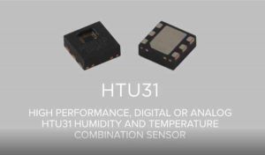
Nowadays, the requirements for industries such as medical, consumer electronics, industrial, and appliances force the manufacturers to come out with more efficient sensors, that also need to take into account environmental conditions and user expectations. The HTU31, by TE Connectivity, is an interesting, highly accurate digital sensor for relative humidity and temperature, ready to be deployed in harsh environmental conditions.
The HTU31, as described by TE Connectivity, “is one of the smallest and most accurate humidity sensors on the market”. With 20+ years of experience, they promise with this sensor fast response time, low hysteresis, high precision measurements and reliable performance even when the environmental conditions go to an extreme, regarding both temperature (-40 ºC to 125 ºC) and humidity (0% to 100% RH).
But what exactly are we looking at, when it comes to characteristics?
Typical accuracy ±2% RH and ±0.2 °C
Active current consumption of 450 µA, with sleep modes down to 0.05 µA
Application-friendly voltage range, from 3 V to 5.5 V (6 V peak)
Power dissipation as low as 3.78 µW (digital version) or 15 µW (analog version)
Fast response time
Compact 6-Pin DFN package (reflow solderable, compatible with automatic assembly procedures), measuring only 2.5mm x 2.5mm x 0.9mm. Lead free
Both digital (fast I2C interface with 2 configurable addresses) and analog interface versions
Quick recovery after long periods in the saturation phase
Full interchangeability with no calibration required in standard conditions
Fully calibrated, temperature compensated measurements
This is the Carleton Weather Station, at least the computer end of it. The data acquisition system is to the left and the web server is the Mac computer. It is located in Olin 206.
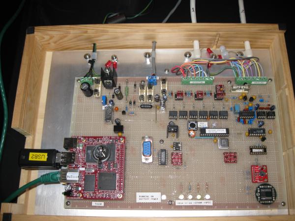
This is the Carleton Weather Station’s data acquisition system. This replaced a 1995 Mac and some daq boards. This daq system is based on a Microchip PIC18F876. It has its own battery back-up.
This is a more detailed picture of the Weather Station daq board. The board in the lower left interfaced with the PIC and the web server. It also stores the data in the thumb drives.
This shows two of the sensors located on the roof of Olin Hall. The black tube pointing down houses the humidity sensor. Inside the ‘stacked plates’ is the temperature sensor. The view is looking east, and in the distance you can see the Carleton wind turbine. (lower right center)
Located on this mast are the wind direction sensor (left side), solar radiation sensor (top center), and wind speed anemometer (right). These are located on the roof of Olin Hall.
This is the rain gauge located on the roof of Olin Hall. Inside the top is a funnel which directs water collected in the 8″ opening down to the tipping bucket.
This is what the inside of the rain gauge looks like with the funnel removed. It is kind of hard to see but the black object in the middle is the tipping bucket. When one side fills with .01″ of rain it tips to the other side and sends a pulse to the data acquisition system. The daq system counts these pulses and displays them to the nearest .01″ of rain (or melted snow in the winter).
This is a new instrument platform under development to also go on the roof of Olin Hall. The left shows two radiometer instruments on a pan-tilt platform that will track the sun. The sun will be the light source and between the sun and the sensors is the atmosphere, which will be sensed at different wavelengths to monitor its changes relating to solar absorbtion. On the platform on the top are two pyranometers, a UV radiometer, a sky temperature sensor, a full sky camera, a Photosynthetically Active Radiometer (measures the visible light spectrum used by plants), an ambient light sensor, and some special sensors. An additional boom extends out with a special barometric pressure head that compensates for wind effects, a black globe sensor that simulates how outdoor animals might experience sunlight, a microphone to ‘hear’ thunder, and a detector that can differentiate between different types of precipitation. There are also lightning detectors that work like AM radios to detect static as well as an optical sensor that can detect the flash. Also located on this structure are precipitation sensors that will signal the first drop of rain, an antenna for the Lyman Lakes buoy, and a webcam allowing users to view the inner part of campus.
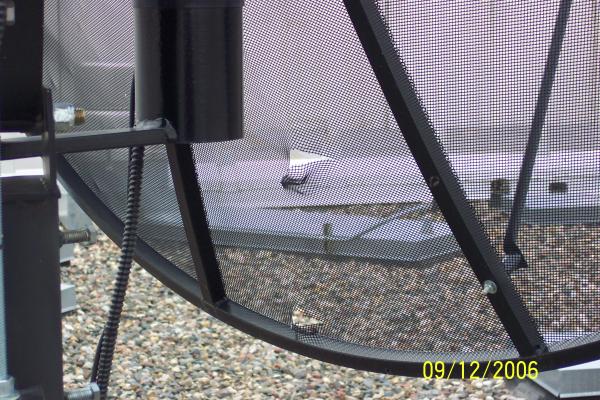
Note the two holes in the small radio telescope dish antenna located on the roof of Olin Hall. These are the result of the recent hail storm that blew thru. The top of the dish has lots of dimples in it also.
The new sidereal clock located in the 16″ dome. It gets its time from GPS and automatically dims as the dome gets darker or via wireless control.
This is the wireless control pendant that allows the operator to rotate the dome clockwise or counter-clockwise and then stop its rotation. It also has buttons to control the intensity of the sidereal clock display and an indicator to notify when the RF link’s battery is low. The pendant also has the cool abiltiy to illuminate all the buttons red when it is picked up. It does this by sensing the hand’s capacitance. This allows the operator to see the buttons while working in a darkened dome.
Located in the center of the aluminum cylinder is a Burr-Brown OPT101 photodiode/amplifier chip. It is powered by a 9 volt battery inside the box, and the signal is tapped off and output on a BNC connector. The cylinder accepts 12 mm optical filters such as narrow bandwidth interference types.
This is a handy op amp amplifier box for use in labs. It is battery powered and allows differing gains to be selected. It uses a precision op amp powered by a 9 volt battery. The negative voltage is generated by a charge pump converter. The label on the diecast aluminum box was created in Microsoft WORD and printed on a sheet of label paper and then cut to fit the top.
This is the guts of a time delay relay for a dc powered compressor. It uses an 8 pin Microchip PIC microcontroller to monitor the 24 volt dc supply. If the supply goes out of range the relay turns off. Once the power is restored at its operating specification there is a 10 minute delay before the relay is turned back on. This gives the compressor time to equalize pressures before trying to start again as might typically happen after a power outage.
As technology changes from time to time, the need to deliver networks with high throughput and high efficiency becomes a major necessity. The latest generation of wireless network technology, WiFi 6 or 802.11ax offers not just faster speeds as generational changes, but higher-efficiency Wi-Fi for better coverage, improved capacity, and reduced network congestion.
To provide developers with a platform that allows them leverage on the speed and efficiency offered by these new wireless technology, 8Devices has employed their many years of experience in hardware and embedded software to birth a WiFi 6 system-on-module and a corresponding WiFi 6 development kit called the Mango SoM and Mango DVK.
The Mango SoM is powered by Qualcomm IPQ6000/IPQ6010 quad-core Cortex A53 processor and supports high power dual-band 2×2 MiMo 802.11ax. It has many peripheral interfaces that can be configured as general-purpose I/O pins and others.
The SoM runs OpenWrt Linux and is considered ideal for routers, gateways, and access points. It is available in both the commercial and industrial temperature range (Mango and Mango-I respectively), in case you’d want to use it for applications that require extended temperature range.
The i.MX RT1064 is one of the highest performing Cortex-M7 solution delivering 3020 CoreMarks (when running core at 600 MHz). In addition to the high-speed performance it provides fast real-time responsiveness and offer several low power modes.
This is a great option when microcontrollers no longer offers sufficient performance and there are reasons to not fully transfer into the Linux universe with an application processor.
Highlights
High-performing Cortex-M7, up to 600 MHz
Fast real-time response with ultra-low latency
On-board 1ZM Wi-Fi/BT option
Multimedia Functionalities
The i.MX RT1064 has the most comprehensive multimedia functionality among our microcontroller modules including great audio, 2D video accelerator, pixel processing and camera sensor.
Wide Range Of Connectivity Options
There is an on-board Wi-Fi/BT option with Murata’s 1ZM (LBEE5QD1ZM) module, based on NXP 88W8987 chipset. It is a dual-band Wi-Fi 802.11a/b/g/n/ac + Bluetooth 5.1 module.
There is also a wide range of advanced off-board connectivity options with other Murata Wi-Fi and Bluetooth modules.
Temperature Range
Our iMX RT1064 uCOM board is available in commercial / industrial temperature range, 0 to +70 / -40 to +85 degrees Celsius. The industrial (temperature range) version is suitable for always-on applications.
The Teseo-LIV3F is a standalone positioning receiver IC that works simultaneously in multiple constellations (GPS, Galileo, Glonass, BeiDou and QZSS), being an easy to use GNSS (Global Navigation Satellite System) module. It brings the proven accuracy and robustness of the Teseo chips into the hands of everyone.
Besides being able to integrate this module into your projects, the EVB-LIV3F standalone solution allows you to evaluate its performance using only a computer, pretty easy!
Looking at the specifications of the Teseo-LIV3F, there is:
Simultaneous multiconstellation
-163 dBm tracking sensivity
1.5 m CEP position accuracy
Operating voltage range from 2.1 V to 4.3 V
UART and I2C port available
Tiny LCC 18 pin package, measuring 9.7 mm by 10.1 mm
Extended operating temperature range, from -40 ºC to 85 ºC
Free firmware configuration
17 µW standby current and 75 mW tracking power consumption
Aside from the list of specs, there are some other interesting functionalities to highlight: firstly, the on-board TCXO (Temperature Compensated Crystal Oscillator) allows for superior accuracy and a reduced TTFF (Time to First Fix) that relies on its dedicated 32 kHz RTC (Real Time Clock) oscillator. Other interesting feature is the embedded 16 Mb flash memory, which enables the chip to offer many interesting extra functionalities, such as data logging, 7 days autonomous assisted GNSS, besides firmware reconfigurability and upgrades. The Teseo-LIV3F also provides the Autonomous Assisted GNSS, which enables it to predict satellite data based on previous observation of the satellite. Lastly, the module is a certified solution, that optimizes the time to market of the final applications, with a wide operating temperature range.
Driving innovation in energy harvesting, e-peas has gained another major endorsement for its cutting-edge technology. The company’s highly optimised power management ICs are set to feature in a large scale remote monitoring application that is being rolled out across New York.
IoT solutions provider MCCI has incorporated the e-peas AEM10941, which specifically targets solar powered implementations, into a new environmental sensor module that it is about to start deploying. As part of a community-funded project, these sensor nodes will be placed in economically disadvantaged neighbourhoods within the city boroughs of Brooklyn, the Bronx and Harlem, where air pollution levels are extremely high.
The MCCI modules each feature PM2.5 particulate and VOC sensing devices, plus temperature and humidity sensors. Located on utility poles, these compact form factor units will dynamically gather real-time data relating to their surroundings every 6 minutes. This data will be transmitted back to a network hub via LoRaWAN connectivity for subsequent analysis. With prototyping almost completed, the pilot scheme is due to go into operation before the end of the summer.
Thanks to the AEM10941-based energy harvesting circuit, it has been possible to avoid powering the sensor module via a battery (and the inconvenience of battery replacement). This highly advanced e-peas power management IC can deal with the DC power output from up to 7 solar cells and supply hardware with two independent regulated voltages. It can start operating from a very low threshold – needing an input voltage of just 380mV and a 3µW input power. Supplied in a space-saving 28-pin QFN package (with 5mm x 5mm dimensions), the IC incorporates all the active elements needed for an energy harvesting subsystem, including a boost converter and two LDOs. Only 7 passive components (5 capacitors and 2 inductors) are needed to accompany it, thereby keeping the bill-of-materials costs down.
Many applications these days require a small or bigger display, either for displaying the time, temperature or other sensor value, or even just a battery indicator, in a simple manner. With them, you usually want some sort of animation, such as a blinking, so that the system feels more alive and interesting to the user. The problem is, with the nature of these devices, when you get to a lower power state in your microcontroller you lose the ability to display anything at all, and animating? Only in your dreams. A possible solution is to have a separate component dealing with the display state, so that your MCU can go to sleep and save power. Regarding this problem, the new PIC24F ‘GU/GL’ promises to help you out and bring much more to the table!
The PIC24F ‘GU/GL’ family is a set of extremely low power (XLP) microcontrollers from Microchip, that enable you to create some innovative applications, both with and without displaying capabilities. Being packed with 14 types of Core Independent Peripherals (CIPs) that can work even on low power saving modes, this series of MCUs offers ultra low power modes, just what you need for your battery powered projects. Besides that, there are also code protection features and this set of MCUs will also work with the CryptoAuthentication devices, in order to add security to your application in a secure manner.
Besides the interesting set of specs, remember us mentioning a little help with the displays? Well, one of the core independent peripherals from this series is a LCD with autonomous animation. But what exactly does this mean? As the name implies, you can use the integrated LCD driver from your MCU, independently of the power mode your microcontroller is in. Since it is detached from the CPU, it performs animations even when the CPU is in a sleeping state! Besides that, the MPLAB Code Configurator (MCC, for short) allows you to design an interface for the display with minimal fuss, eliminating the time consuming task of mapping pins from the seven segment display.
Regarding applications, you can do a lot with this set of MCUs, such as applications where a display is necessary, such as automotive clusters, thermostats, measurement units and even medical devices. With its security capabilities, you can dive into secure IoT projects, such as smart sensors, in-home displays and fitness monitors / wearables. Devices designed for harsh environments are also a reality, such as industrial sensors and monitors, fault detectors and control / automation projects. Lastly, you can also take advantage of its low power capabilities with handhelds and projects in remote areas where access may not be easy. Regarding the pricing, MCUs are available for as little as $0.97, and for development boards with an LCD display you are looking at around $45.
Forlinx has published details on the headless sandwich-style OK1028A-C SBC with a FET1028A-C module powered with a 1.5GHz, dual-core, Cortex-A72 LS1028A. The SBC comes with the support for the LVDS interface to enable HMI (Human-Machine Interface) applications.
The FET1028A-C module has the support for five 2.5GbE ports but the OK1028A-C SBC is limited to five 1GbE ports. The OK1028A-C is equipped with a display interface and TSN (Time-Sensitive Networking). TSN is the technique that is often used as an economic alternative to proprietary Fieldbus technologies. It provides Ethernet time synchronization for guaranteed latency and Quality of Service (QoS).
The 65 x 42mm FET1028A-C module comes with 2GB DDR4 and 8GB eMMC memory. Other features include the support for DP 1.3 and eDP 1.4 interfaces up to 4Kp60. Available I/Os are 2x USB 3.0, 2x CAN FD, 4x UART, 6x I2C, 6x I2S, 2x SPI, and SD 3.0. The module has a robust operating temperature range of -40 to 85℃.
The SoM provides a 4-port TSN switch with 2.5GbE support as well as support for a fifth 2.5GbE port and a GbE port. Five of these native GbE ports can be configured by SerDes with SATA III and 2x up to 8GT/s PCIe 3.0 in various combinations with SGMII and QSGMII Ethernet.
Overview of SoM FET1028A-C :
CPU: NXP LS1028A, Dual-core Cortex-A72 @1.5GHz
Memory: 2GB DDR4, 8GB eMMC
Interface:
1x Display Port; DP1.3 and eDP 1.4, up to 4Kp60
eSDH; SD3.0
Ethernet; CPU has 6 native MAC, up to 2.5Gbps
PCIe 3.0; up to 8GT/s, configured by SerDes
SATA 3.0; up to 6Gbps , configured by SerDes
USB 3.0; up to 5Gbps
UART; can support 1x DUART or 4x UART
OS: Ubuntu 18.04
Power input: DC 12V
Working temperature: -40℃~ +85℃
Dimensions: 42mm×65mm
Ubuntu18.04 is well supported with apt-get installation on this board. Targeted applications are in the field of industrial IoT, TSN, SD-WAN, 5G CPE, edge computing gateway, IP-PBX, smart factory, information security, intelligent transport, power management and, various other fields.
Axiomtek – a world-renowned leader relentlessly devoted in the research, development and manufacture of series of innovative and reliable industrial computer products of high efficiency – is pleased to announce the AIE100-903-FL-NX, its ultra-compact and state-of-the-art edge AI system. The high-performance AIE100-903-FL-NX is powered by the NVIDIA® Jetson Xavier NX module which has a powerful 6-core NVIDIA® Carmel ARM® v8.2 64-bit processor and 384-core NVIDIA® Volta GPU architecture with 48 Tensor cores; in addition, it integrates Allxon Device Management Solutions (Allxon DMS) to provide a cost-effective and simplified device management solution with comprehensive remote management capabilities. The AIE100-903-FL-NX is ideal for smart city, smart manufacturing, smart retail, and other intelligent edge AI applications.
The AIE100-903-FL-NX is a waterproof, fanless NVIDIA-based AI edge inference system designed for AI computing and deep learning applications, such as behavior analytics, face recognition and vehicle analysis. Due to its rugged design, the ultra-compact edge computing device can operate in harsh environments with a wide range of temperatures from -30°C to +50°C and can withstand vibration up to 3 Grms. In addition, it offers an optional waterproof IP42-rated cover kit for enhanced protection in semi-outdoor environments,” said Annie Fu, the product manager of Product PM Division at Axiomtek. “Besides the outstanding hardware solutions, the AI-powered AIE100-903-FL-NX is integrated with cloud-based Allxon DMS to provide remote management for convenient real-time control on devices. Allxon DMS offers rapid deployment and integration on multiple operating systems, reduces system downtime and maintenance costs, and further provides a wide breadth of centralized cloud device management. This industrial edge AI system is the best choice to simplify the large-scale deployment of AIoT platforms.
The AIE100-903-FL-NX offers support for NVIDIA® JetPack 4.4 for ease of development in AI computing and deep learning applications. It has abundant I/O connectivity, including one USB 3.1 Gen2 port, one USB 2.0 port, one Micro USB port, one GbE LAN port, one GbE PoE port and one HDMI 2.0 port supporting 4K2K. It also has one recovery switch, one reset button, one power button, one 12V DC power input and two SMA-type antenna openings. Users can use the recovery switch and Micro USB to easily flash the image without opening the chassis. The AIE100-903-FL-NX has a 16GB eMMC onboard and is equipped with one M.2 Key M 2280 SSD slot with PCIe x4 NVMe and one Micro SD slot for real-time massive workload processing at the edge. Furthermore, the AIE100-903-FL-NX has one full-size PCIe Mini Card slot supporting USB and PCIe signal and one SIM slot for 3G/4G, GPS, Wi-Fi and Bluetooth connections.
A digital thermometer is a good choice of project for beginners who just stepped in to the world of microcontrollers because it provides an opportunity to learn using sensors to measure the real world signals that are analog in nature. This article describes a similar project based on a PIC16F688 microcontroller and an LM35 temperature sensor. LM35 is an analog sensor that converts the surrounding temperature to a proportional analog voltage. The output from the sensor is connected to one of the ADC channel inputs of the PIC16F688 microcontroller to derive the equivalent temperature value in digital format. The computed temperature is displayed in a 16×2 character LCD, in both °C and °F scales.
Theory
The LM35 series of temperature sensors are produced by National Semiconductor Corporation and are rated to operate over a -55 °C to 150°C temperature range. These sensors do not require any external calibration and the output voltage is proportional to the temperature. The scale factor for temperature to voltage conversion is 10 mV per °C. The LM35 series sensors come in different packages. The one I used is in a hermatic TO-46 transistor package where the metal case is connected to the negative pin (Gnd).
The measurement of negative temperatures (below 0°C) requires a negative voltage source. However, this project does not use any negative voltage source, and therefore will demonstrate the use of sensor for measuring temperatures above 0°C (up to 100°C).
The output voltage from the sensor is converted to a 10-bit digital number using the internal ADC of the PIC16F688. Since the voltage to be measured by the ADC ranges from 0 to 1.0V (that corresponds to maximum temperature range, 100 °C), the ADC requires a lower reference voltage (instead of the supply voltage Vdd = 5V) for A/D conversion in order to get better accuracy. The lower reference voltage can be provided using a Zener diode, a resistor network, or sometime just simple diodes. You can derive an approximate 1.2V reference voltage by connecting two diodes and a resistor in series across the supply voltage, as shown below. As a demonstration, I am going to use this circuit in this project. I measured the output voltage across the two diodes as 1.196 V. The resistor R I used is of 3.6K, but you can use 1K too. The important thing is to measure the voltage across the two diodes as accurate as possible.
We need do some math for A/D conversion. Our Vref is 1.196 V, and the ADC is 10-bit. So, any input voltage from 0-1.196 will be mapped to a digital number between 0-1023. The resolution of ADC is 1.196/1024 = 0.001168 V/Count. Therefore, the digital output corresponding to any input voltage Vin = Vin/0.001168. Now, lets see how to get the temperature back from this whole process of converting sensor’s output to 10-bit digital number.
Assume, the surrounding temperature is 26.4 °C. The sensor output will be 264 mV (0.264 V). The output of ADC will be 0.264/0.001168 = 226. If we reverse this process, we have 226 from ADC and we can go back and find the temperature by using the sensor scale factor (10 mV/°C),
temperature = 226 * 0.001168 (V/Count) / 0.01 (V/°C) = 26.4 °C
If you want to avoid floating point math in your program, just use,
temperature = 226 * 1168 = 263968
While displaying this, you need to put a decimal at the fourth place from the left. So the calculated temperature is 26.3968°C, which is pretty close to the actual one. The difference is caused by quantization and rounding errors. In this project, we will display temperature accurate to one decimal place, i.e., we will divide the above number by 1000 to get 263. So the temperature will be displayed as 26.3 °C.
Once you have derived the temperature back in °C, you can convert it to °F using a simple equation,
temperature in °F = 9 x temperature in °C /5 + 32
In this case, the number you got for °C is scaled by 10 (263 for 26.3), you should use
temperature in °F = 9 x temperature in °C /5 + 320
Since, the number for °C may not be exactly divisible by 5 (such as 263 is not), you can further eliminate the floating point by scaling it one more time by 10. So the new equation will be,
temperature in °F = 9 x temperature in °C x 10 /5 + 3200
or, temperature in °F = 18 x temperature in °C + 3200 = 18 x 263+3200 = 7934
79.34 °F is equivalent to 26.3 °C. In this project, it will be displayed as 79.3 °F.
Circuit Diagram
An external reference voltage to the internal ADC of PIC16F688 can be provided through RA1 I/O pin. The output from the LM35 sensor is read through RA2/AN2 ADC channel. The temperature is displayed on a 16×2 character LCD that is operating in the 4-bit mode. A 5K potentiometer is used to adjust the contrast level on the display. The detail circuit diagram is given below. Note that the PIC16F688 uses its internal clock at 4.0 MHz.


 . Featuring a compact 146 x 102 mm (5.78 x 4.01 in) design, this single board computer offers impressive I/O functionality and domain-focused features like CANBus. Advantech’s embedded small form-factor SBC’s are designed to support wide operating temperature ranges (-40 ~ 85°C / -40 ~ 185°F) and harsh environments, making it an excellent choice for applications that require high processing speeds, such as Automated optical inspection machines, passenger information systems, outdoor kiosks, surveillance and medical devices.


 Xavier
